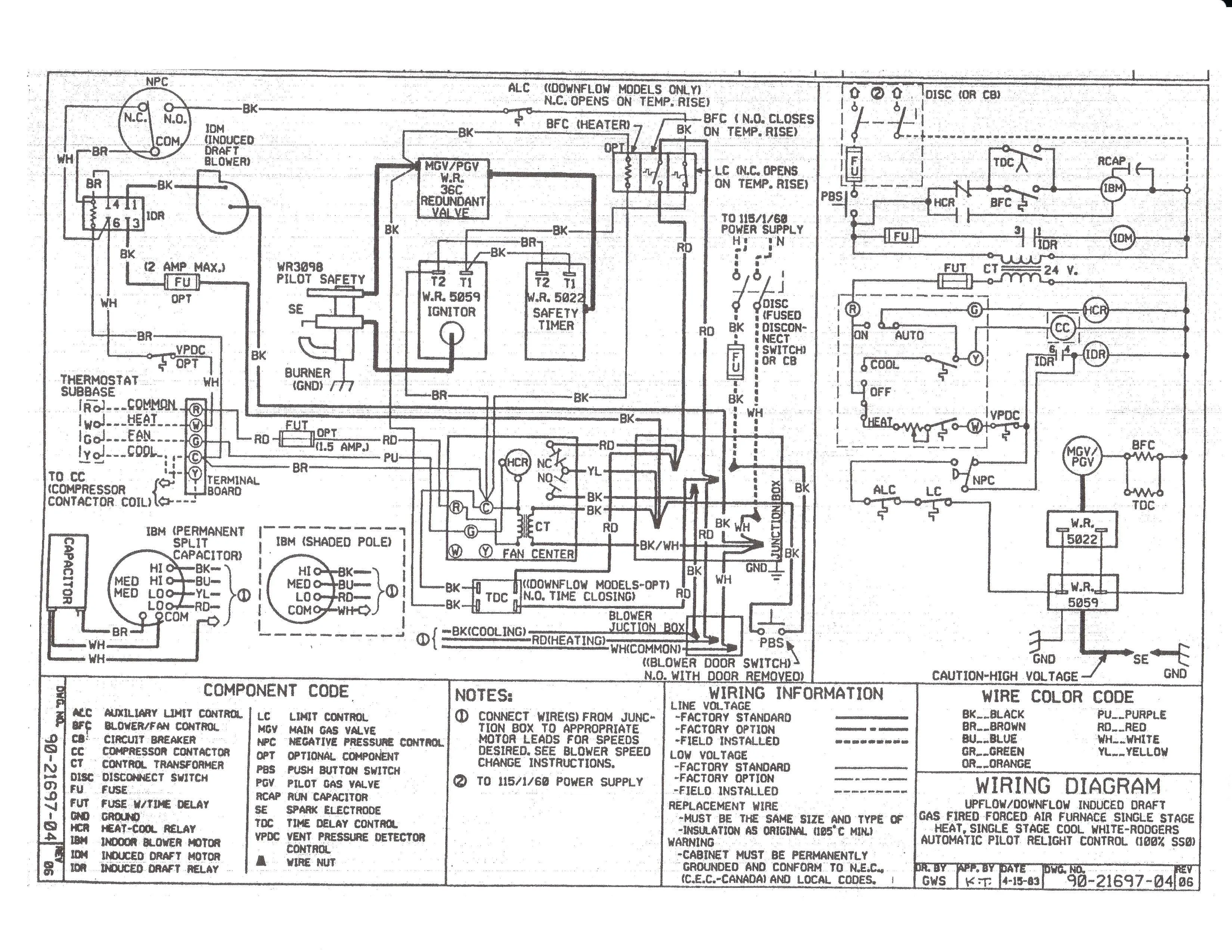
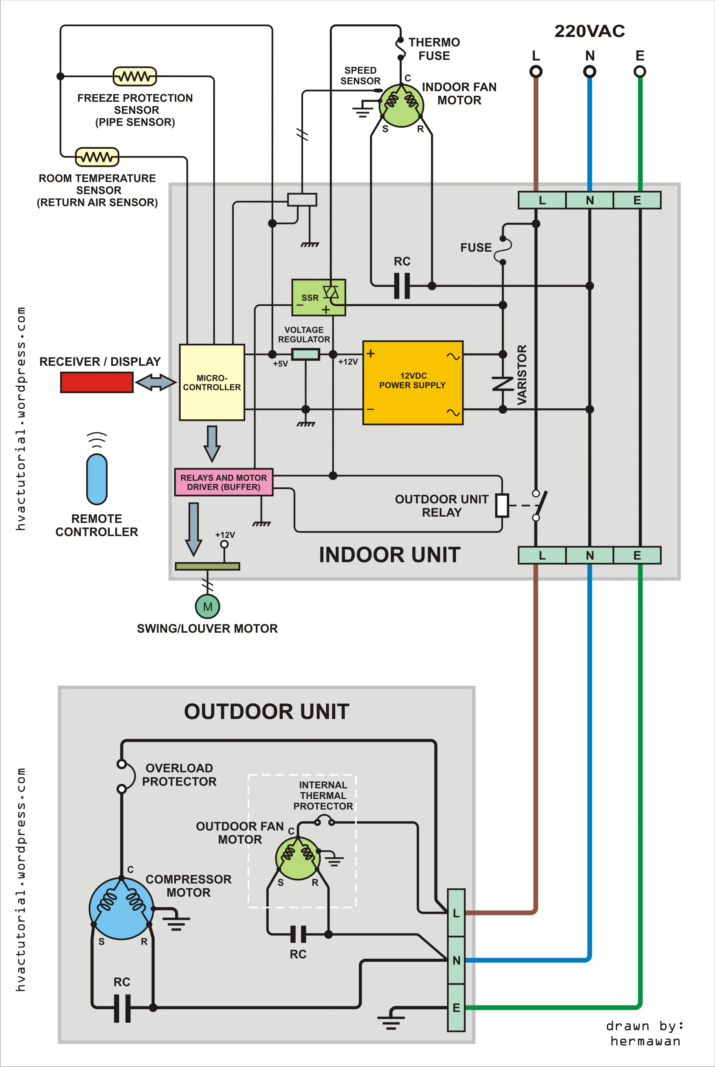
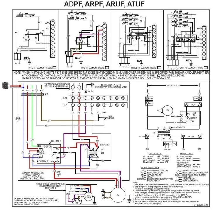
If you have a Goodman AC unit, you may need to access its wiring diagram at some point. The wiring diagram is a detailed schematic that shows the connections of all the electrical components in your air conditioning system. Understanding this diagram is essential for troubleshooting any electrical problems with your AC unit. In this article, we will discuss the wiring diagram for Goodman AC units in detail.
What is a Wiring Diagram?
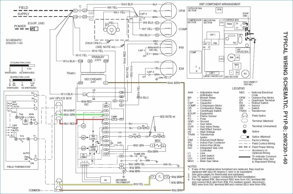
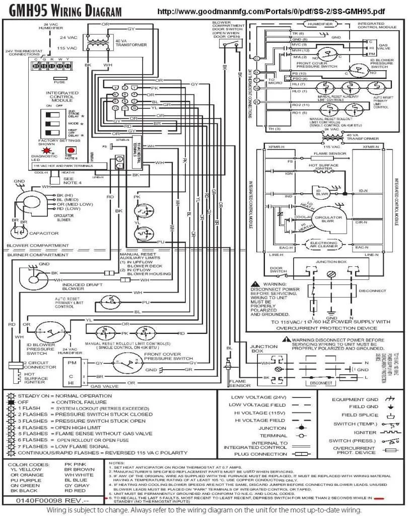
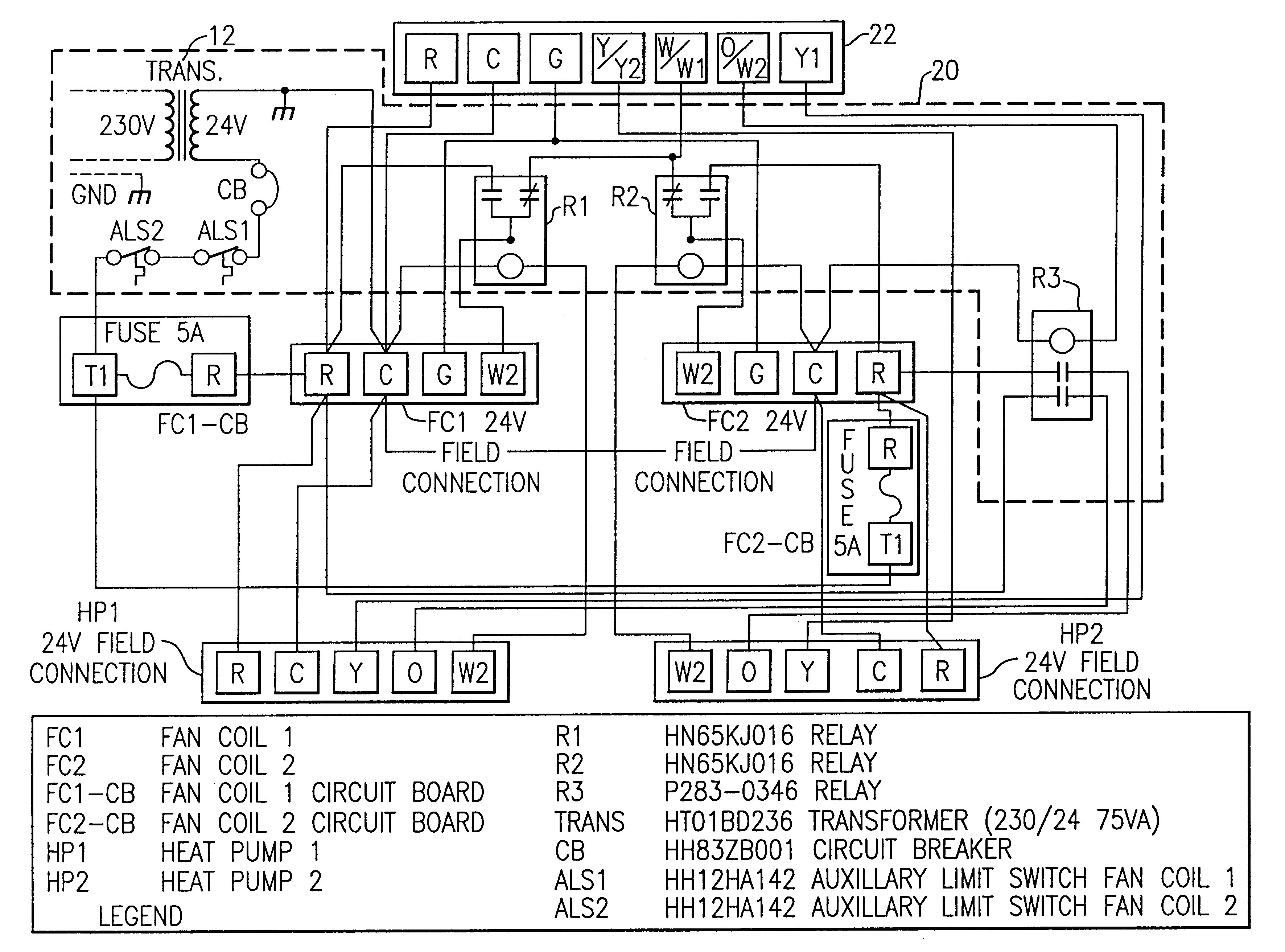
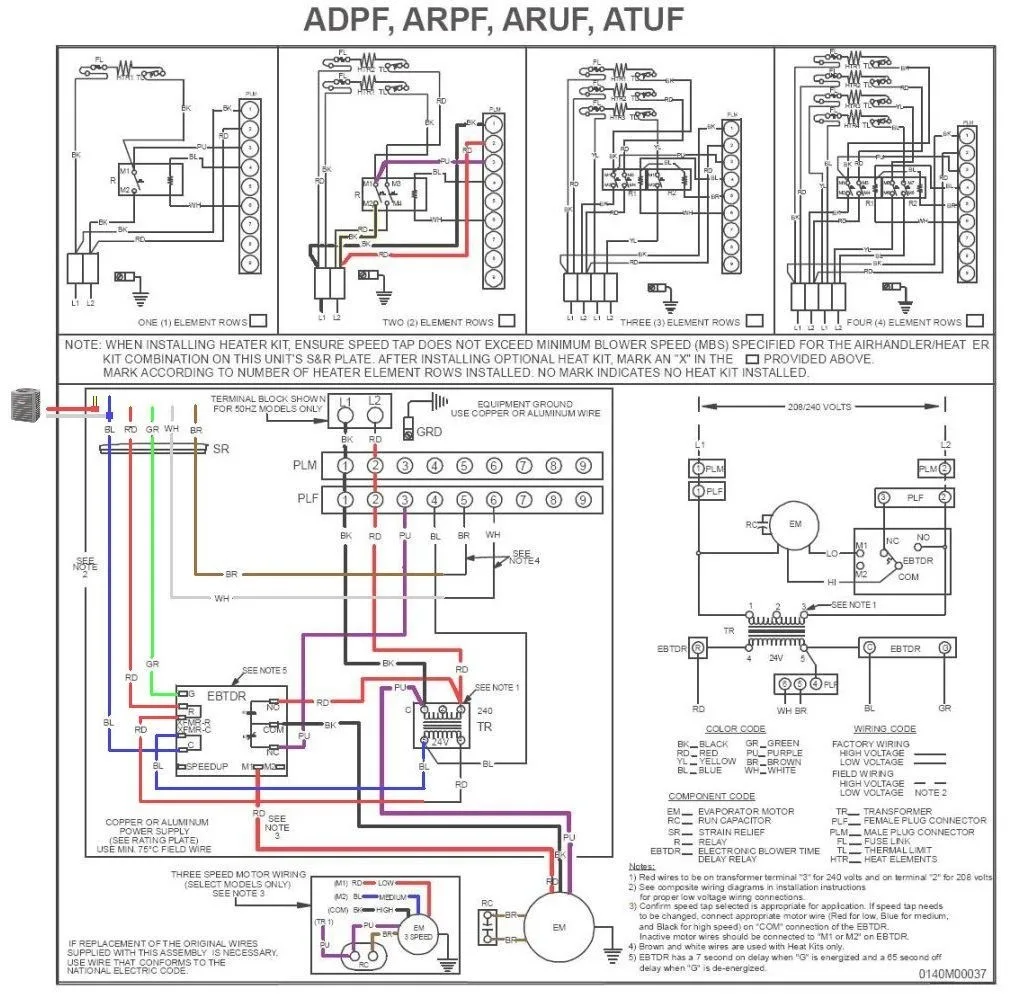
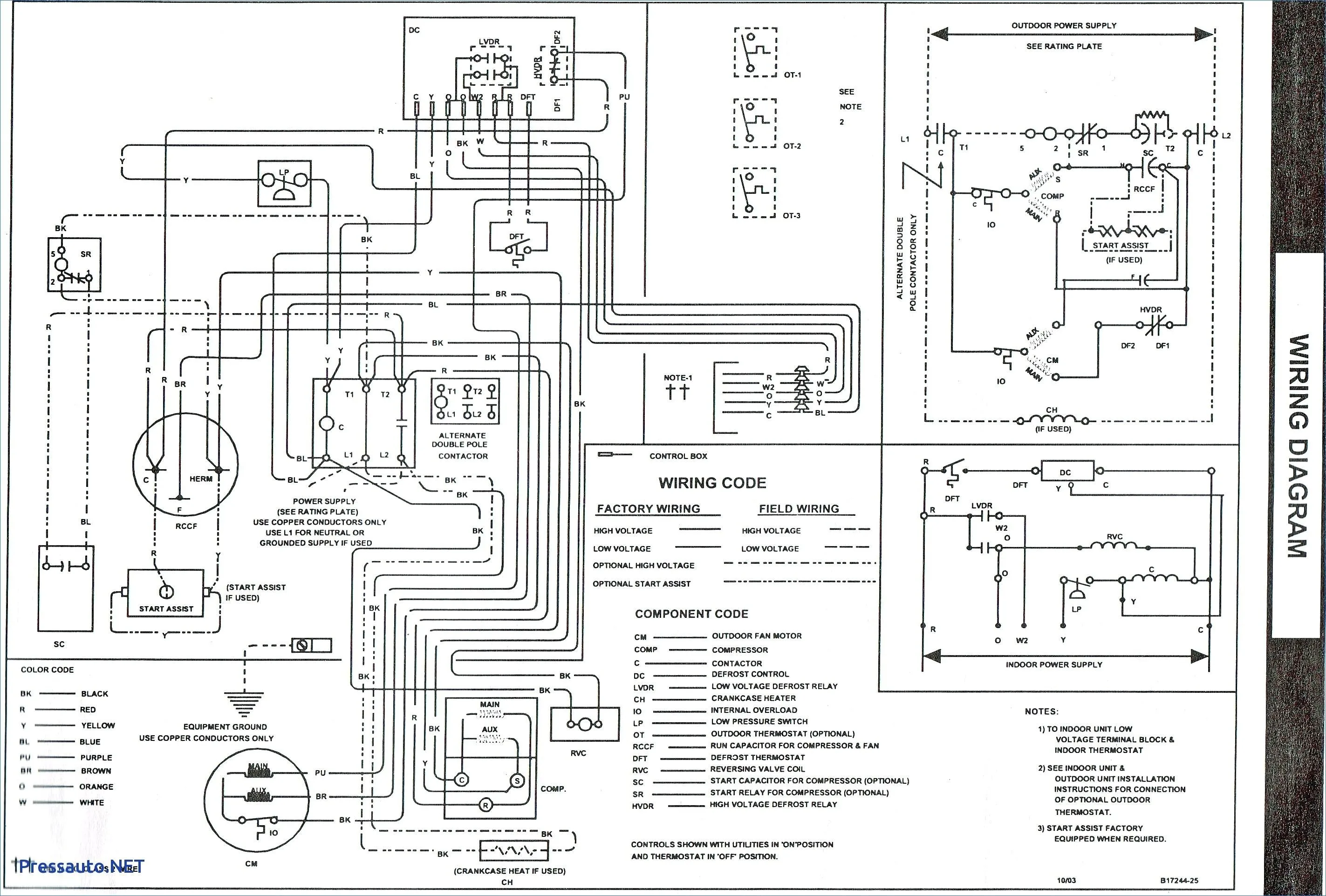
A wiring diagram is a detailed schematic that shows the connections of all the electrical components in an AC unit. It is essential for troubleshooting any electrical problems with your AC unit. Without a wiring diagram, it can be challenging to identify the source of the problem and fix it. The wiring diagram provides a roadmap of all the electrical components, including the compressor, fan motor, thermostat, and capacitors.
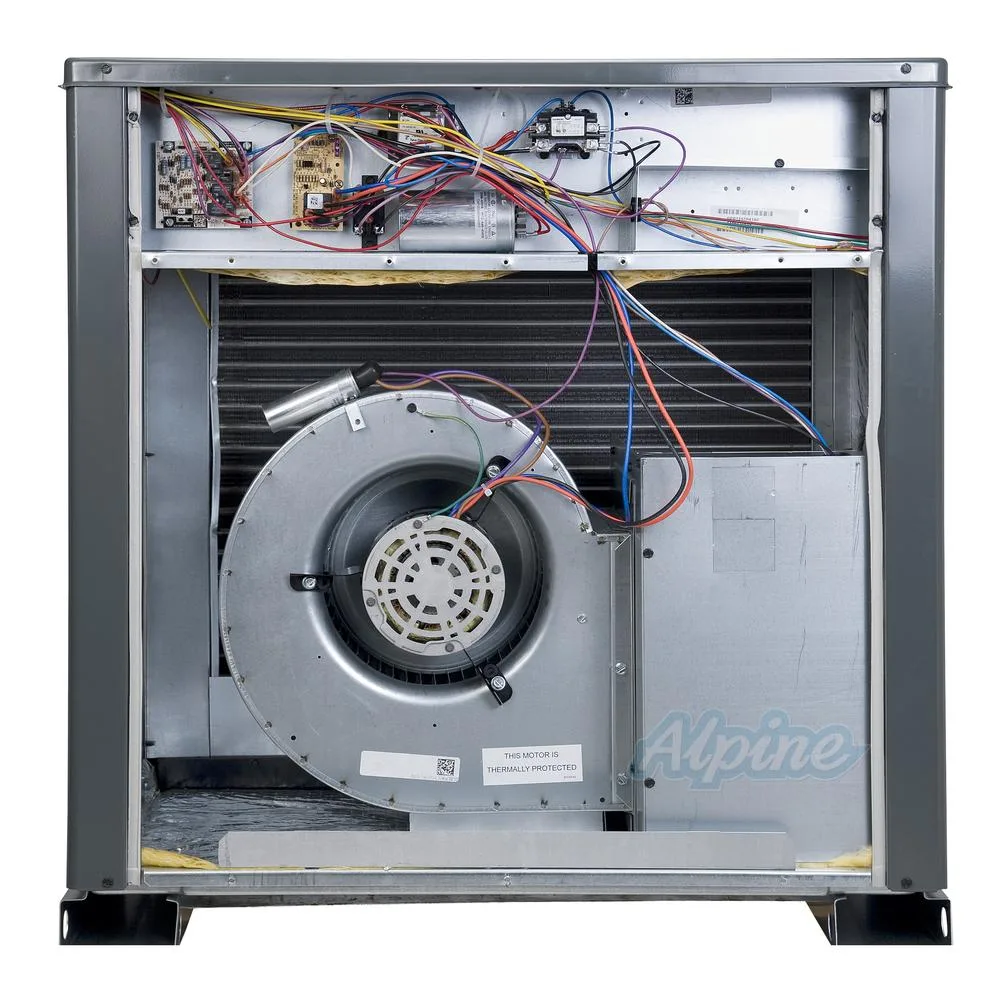
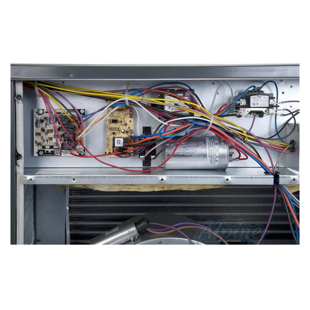
There are two types of wiring diagrams: schematic diagrams and pictorial diagrams. The schematic diagram shows the electrical connections and functions of each component in your AC unit. It uses symbols to represent each component, making it easier to read and understand. The pictorial diagram, on the other hand, shows the physical layout of the components and how they are connected. It is more visual and may be easier to follow for people who are not familiar with electrical symbols.
Understanding the Wiring Diagram for Goodman AC Units
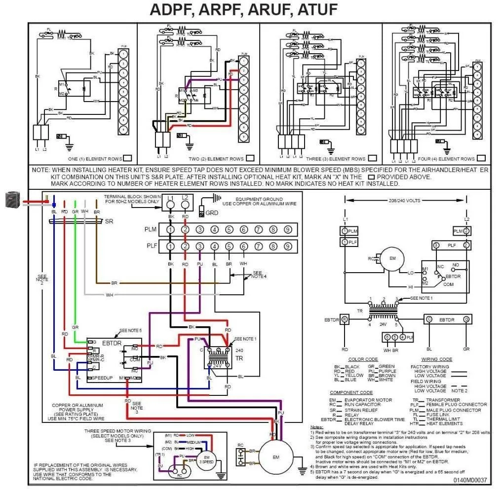
The wiring diagram for a Goodman AC unit is a complex schematic that requires some basic knowledge of electrical systems. It shows the connections of all the electrical components in your AC unit, including the compressor, fan motor, thermostat, capacitors, and relays. Each component is represented by a symbol, and the connections are shown by lines and arrows.
Before you start troubleshooting any electrical problems with your AC unit, you need to have a basic understanding of the wiring diagram. This will help you identify the source of the problem and fix it. The wiring diagram for Goodman AC units is divided into several sections, including the compressor, fan motor, thermostat, and capacitors. Each section has its own set of symbols and connections that are unique to that component.
The Compressor
The compressor is the heart of your AC unit, and its wiring diagram is the most complex. It includes several components, such as the start capacitor, run capacitor, overload protector, and compressor motor. Each component has its own set of connections, and they are all connected to the main power source through a contactor. The wiring diagram for the compressor also shows the connections to the outdoor fan motor, which is responsible for cooling the compressor.
Start Capacitor
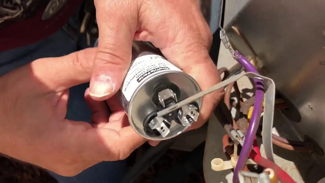
The start capacitor is a component that helps the compressor motor start up quickly. It is connected to the motor through a start relay, which is controlled by the thermostat. The start capacitor provides an extra boost of power to the motor when it starts up, which helps it overcome the initial resistance and start spinning. The wiring diagram for the start capacitor shows its connections to the motor, start relay, and thermostat.
Run Capacitor
The run capacitor is another component that helps the compressor motor run smoothly. It is connected to the motor through a run relay, which is also controlled by the thermostat. The run capacitor provides a steady stream of electricity to the motor, which helps it maintain a constant speed. The wiring diagram for the run capacitor shows its connections to the motor, run relay, and thermostat.
Overload Protector
The overload protector is a safety device that protects the compressor motor from overheating. If the motor draws too much current or gets too hot, the overload protector will trip and disconnect the power to the compressor. The wiring diagram for the overload protector shows its connection to the motor and the main power source.
Compressor Motor
The compressor motor is the component that actually compresses the refrigerant gas in your AC unit. It is connected to the start and run capacitors, overload protector, and the main power source through a contactor. The wiring diagram for the compressor motor shows all of its connections and how it is controlled by the thermostat.
The Fan Motor
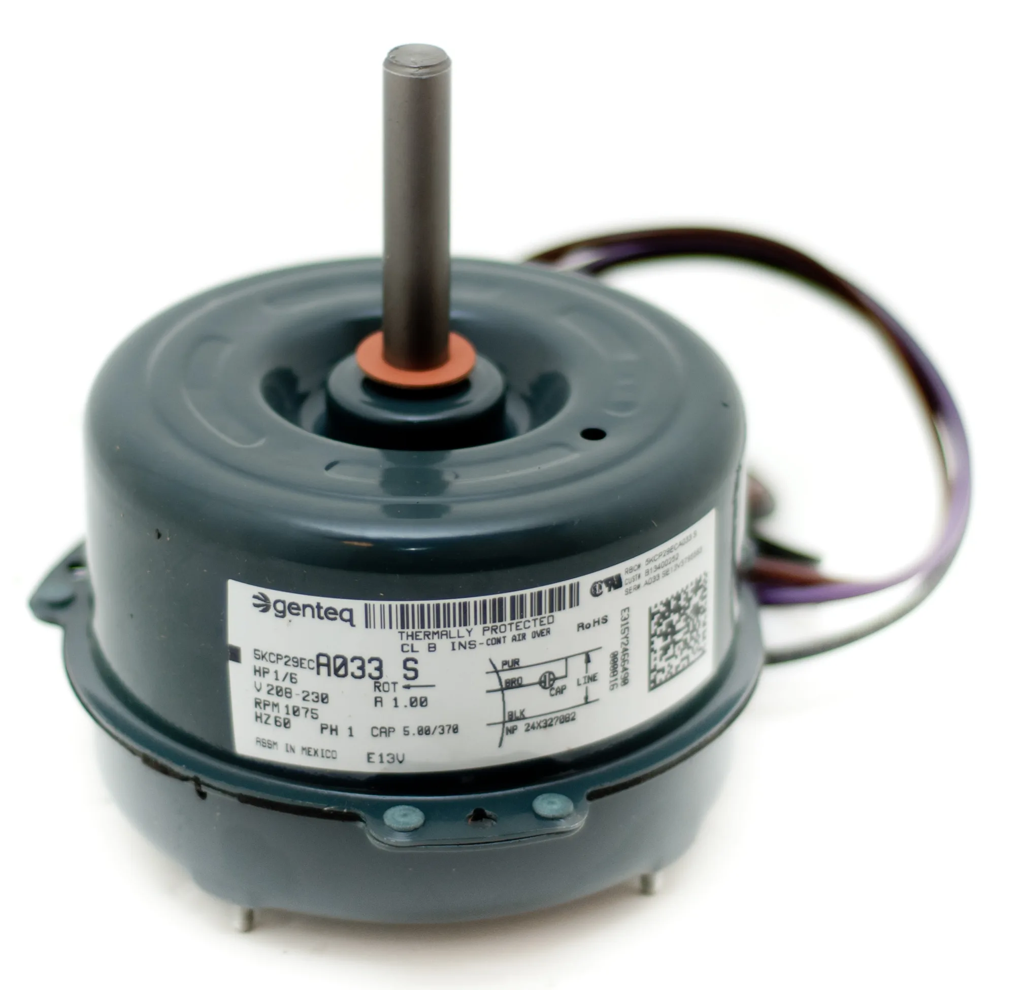
The fan motor is responsible for moving air over the evaporator coil and the condenser coil. It is connected to the power source through a contactor and controlled by the thermostat. The wiring diagram for the fan motor shows its connections to the power source, contactor, and thermostat.
The Thermostat
The thermostat is the component that controls the temperature of your AC unit. It is connected to the start and run relays for the compressor and the fan motor. The wiring diagram for the thermostat shows its connections to the relays, as well as the power source and the temperature sensor.
The Capacitors
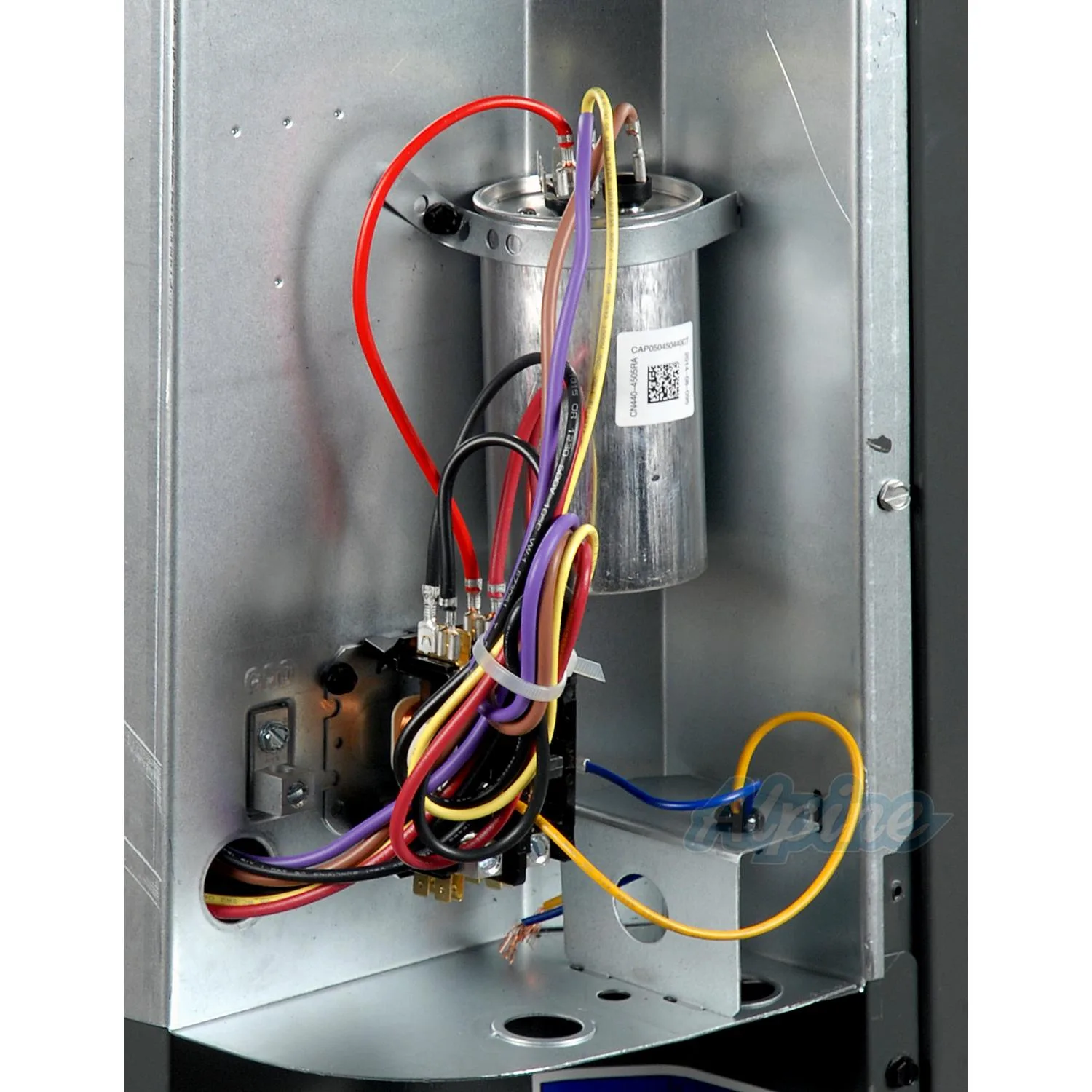
The capacitors in your AC unit provide extra power to the motors when they start up and run. They are connected to the power source through a contactor and controlled by the thermostat. The wiring diagram for the capacitors shows their connections to the motors, contactor, and thermostat.
Frequently Asked Questions
Why do I need a wiring diagram for my Goodman AC unit?
You need a wiring diagram for your Goodman AC unit to troubleshoot any electrical problems that may arise. The wiring diagram provides a detailed schematic of all the electrical components in your AC unit, including the compressor, fan motor, thermostat, and capacitors. Understanding this diagram is essential for identifying the source of any electrical problems and fixing them.
What do the symbols on the wiring diagram mean?
The symbols on the wiring diagram represent the different electrical components in your AC unit. For example, the symbol for the compressor motor looks like a circle with three lines coming out of it. The symbol for the start capacitor looks like two parallel lines with a curved line connecting them. Understanding these symbols is essential for reading and understanding the wiring diagram.
Can I fix electrical problems with my Goodman AC unit myself?
Fixing electrical problems with your Goodman AC unit can be dangerous and should only be attempted by someone with experience working with electrical systems. If you are not familiar with electrical systems, it is best to hire a professional HVAC technician. They have the knowledge and experience to identify and fix any electrical problems with your AC unit safely and efficiently.
How often should I check the wiring diagram for my Goodman AC unit?
You should check the wiring diagram for your Goodman AC unit whenever you experience any electrical problems with your system. You should also refer to the wiring diagram if you are installing or replacing any electrical components in your AC unit. It is essential to have a basic understanding of the wiring diagram to troubleshoot any electrical problems that may arise.
Where can I find the wiring diagram for my Goodman AC unit?
You can find the wiring diagram for your Goodman AC unit in the installation manual or service manual provided by Goodman. These manuals are available online or from your HVAC technician. You may also be able to find the wiring diagram on the inside of the access panel on your AC unit.