Armature winding is an essential part of any electrical system, including motors and generators. The wiring diagram of an armature is critical in understanding how the electrical currents flow inside the equipment. This article aims to provide a comprehensive guide on armature wiring diagrams, explaining their fundamental concepts, types, and applications.
What is an Armature Wiring Diagram?
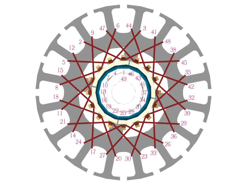
An armature wiring diagram is a representation of an electrical system, illustrating the flow of electric current and voltage. It is used to understand the primary and secondary winding connections of an armature, which is an essential component of motors and generators.
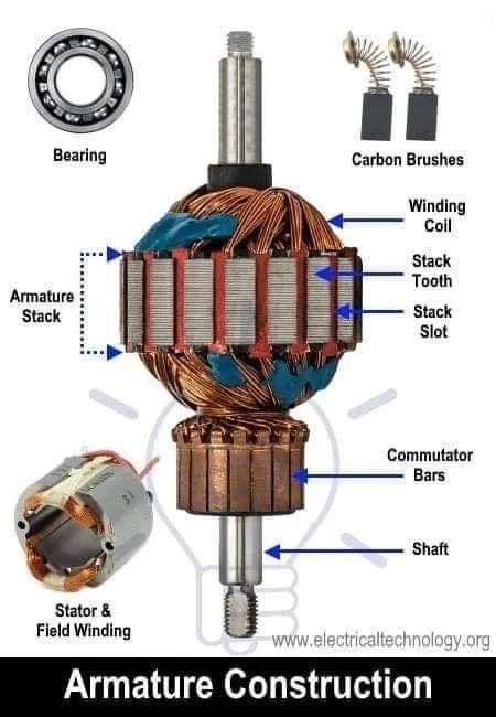
The armature winding is a critical component of any electrical system, as it converts electrical energy into mechanical energy. The armature winding consists of wire coils that generate a magnetic field when electric current flows through them.
Types of Armature Wiring Diagrams
There are two types of armature wiring diagrams, namely lap winding and wave winding.
Lap Winding
In lap winding, the armature winding is arranged in parallel to the magnetic field. The end of the coil is connected to the beginning of the next coil, forming a closed loop. The lap winding diagram is used in DC motors, where the current flows in a single direction.
The lap winding diagram is used when a large current is required, as it can handle greater current loads than other winding types.
Wave Winding
In wave winding, the armature winding is arranged such that the end of one coil is connected to the beginning of the next, but in alternating directions. The wave winding diagram is used in AC motors, where the current flows in both directions.
The wave winding diagram is used when a low current is required, as it can handle smaller current loads than other winding types.
How to Read an Armature Wiring Diagram?
Reading an armature wiring diagram can be challenging, but it follows a simple procedure.
Step 1: Identify the Type of Armature Winding
The first step is to determine the type of armature winding. This can be done by examining the wire coils and identifying their arrangement.
Step 2: Identify the Number of Coils
The second step is to count the number of wire coils in the armature. This can be done by following the wire coils and counting them until they reach the start of the next coil.
Step 3: Identify the Direction of Current Flow
The third step is to identify the direction of current flow in the circuit. This can be done by examining the diagram and following the arrows that indicate the flow of electric current.
Step 4: Identify the Connections between Coils
The fourth step is to identify the connections between the wire coils. This can be done by examining the diagram and following the lines that connect the wire coils.
Step 5: Identify the End Connections
The final step is to identify the end connections of the armature wiring diagram. This can be done by examining the diagram and identifying where the wire coils terminate.
Applications of Armature Wiring Diagrams
Armature wiring diagrams are used in a wide range of electrical systems, including motors, generators, and transformers. They are also used in the construction of electrical appliances, such as air conditioners, washing machines, and refrigerators.
Armature wiring diagrams are essential in troubleshooting electrical problems, as they provide a visual representation of the electrical circuit. They are also used in the design and manufacture of electrical equipment, as they help engineers and technicians understand the electrical properties of the system.
FAQ
Question | Answer |
---|---|
What is an Armature? | An armature is a rotating part of an electrical machine, such as a motor or generator, which generates an electric current when a magnetic field is applied. |
What is an Armature Winding? | An armature winding is a wire coil that generates a magnetic field when electric current flows through it. |
What is a Lap Winding? | In lap winding, the armature winding is arranged in parallel to the magnetic field, and the end of the coil is connected to the beginning of the next coil. |
What is a Wave Winding? | In wave winding, the armature winding is arranged such that the end of one coil is connected to the beginning of the next, but in alternating directions. |
Why are Armature Wiring Diagrams Important? | Armature wiring diagrams are important in understanding the flow of electric current and voltage in an electrical system. They are used in troubleshooting electrical problems and in the design and manufacture of electrical equipment. |
In conclusion, an armature wiring diagram is an essential component of any electrical system, and it is critical to understand its fundamental concepts, types, and applications. Reading an armature wiring diagram can be challenging, but it follows a simple procedure, and once mastered, it can save time and effort in troubleshooting electrical problems. It is crucial to keep in mind that armature wiring diagrams, like any other electrical equipment, should be handled with care and caution to prevent electrocution, fires, and other hazards.