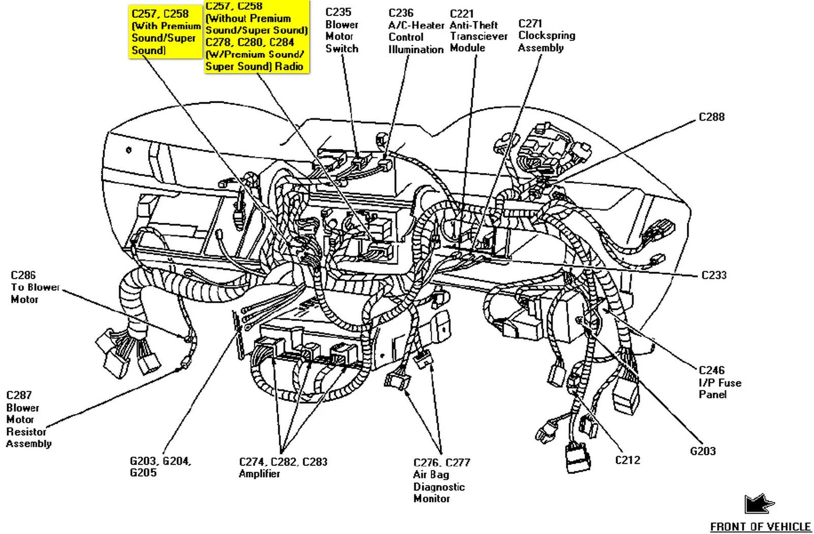
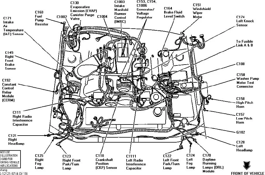
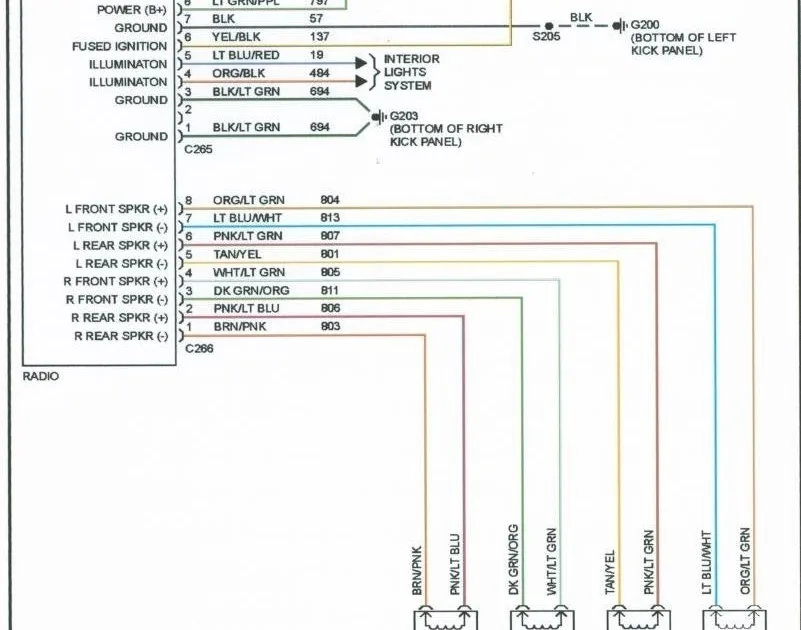
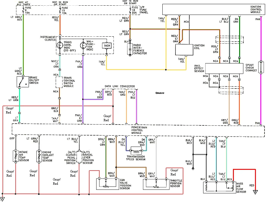
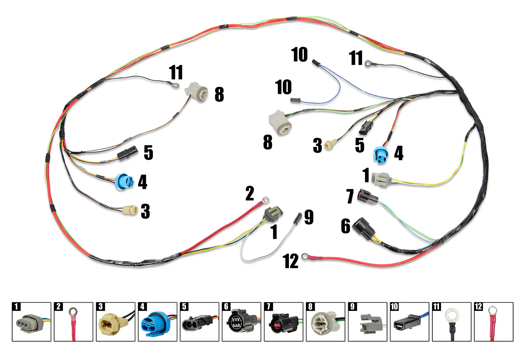
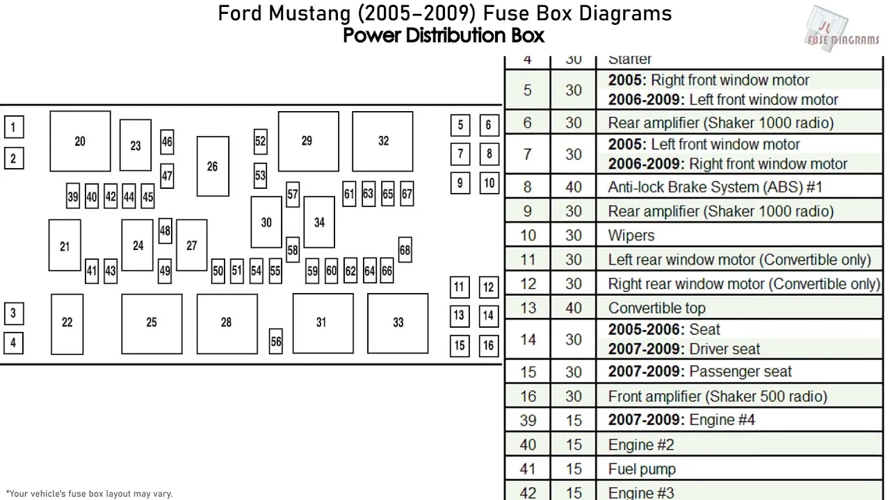
Are you struggling with wiring issues in your 94 Mustang GT? Look no further, this journal article provides a comprehensive guide to the wiring diagram of your 94 Mustang GT, making it easy for you to understand and fix any wiring issues.
Overview
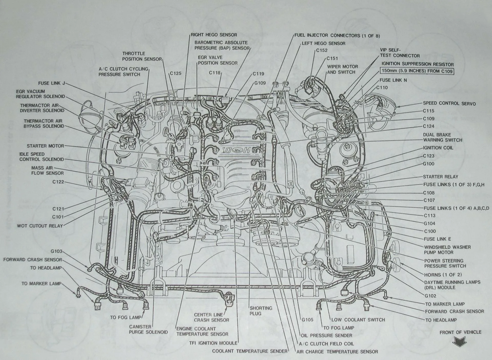
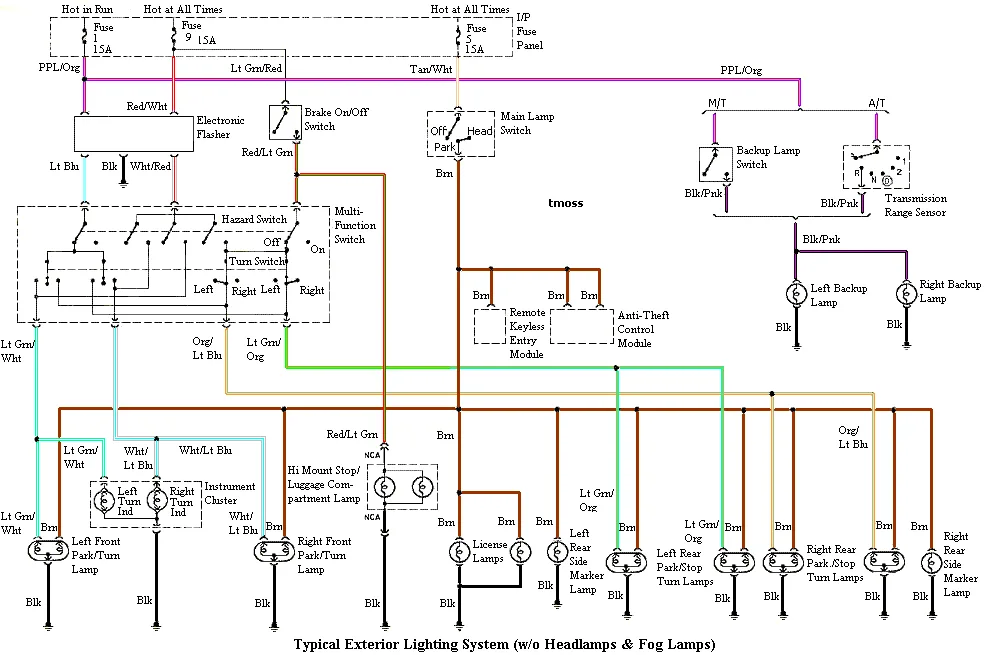
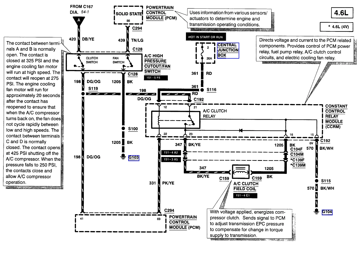
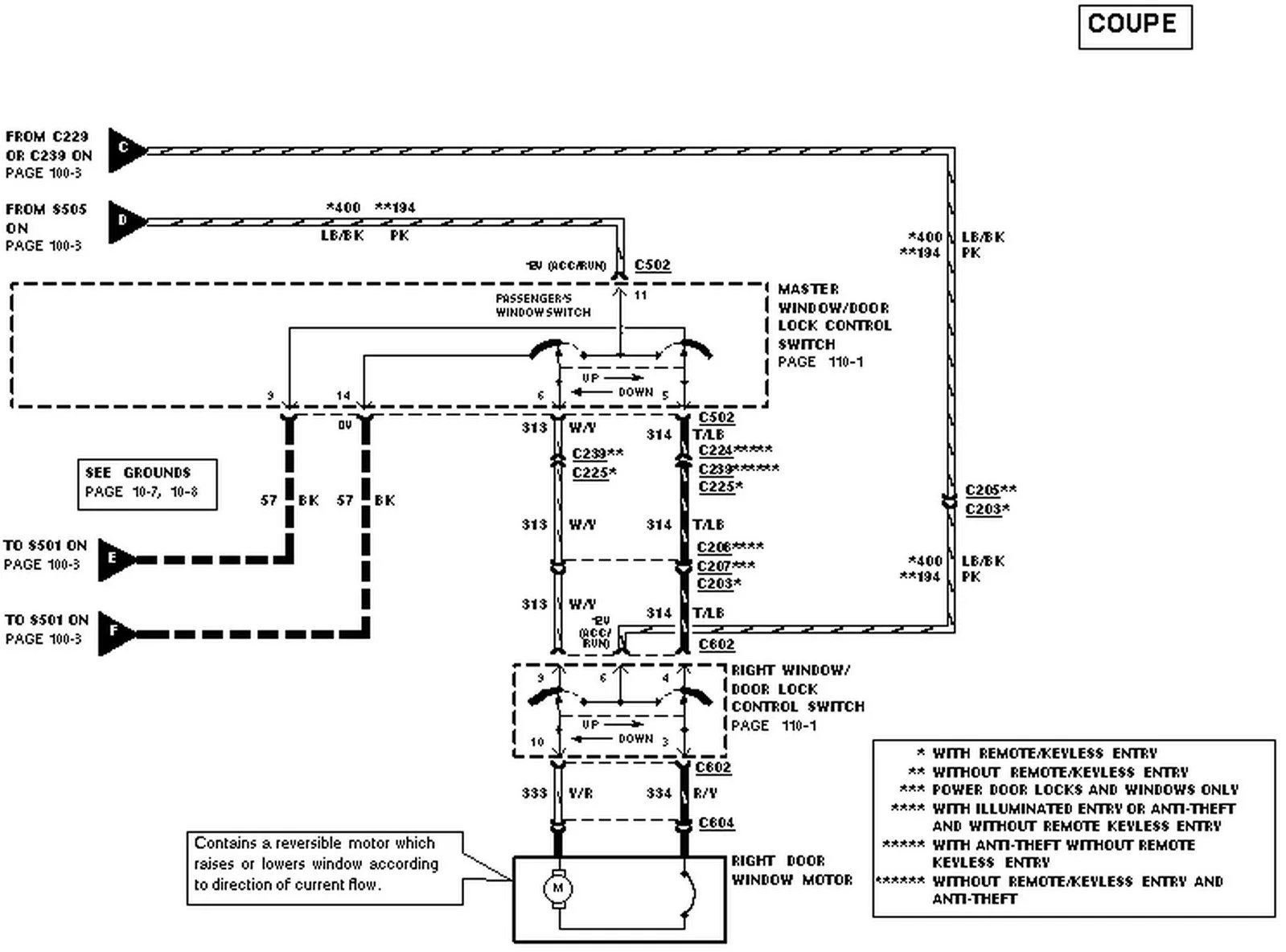
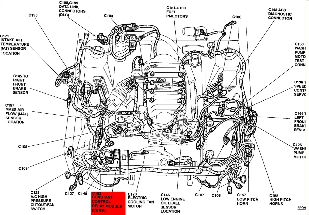
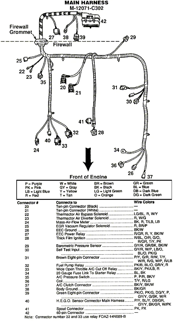
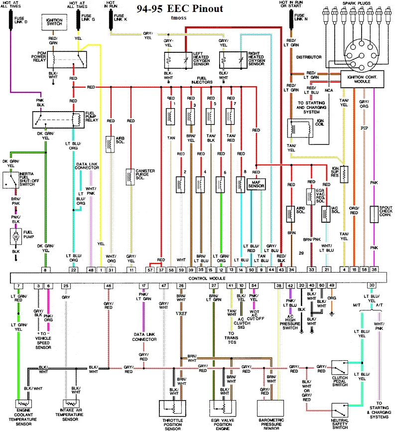
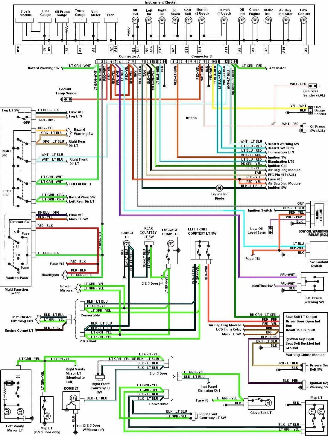
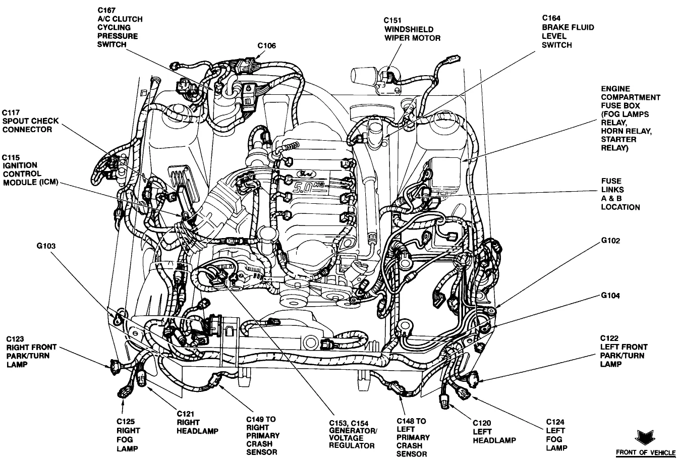
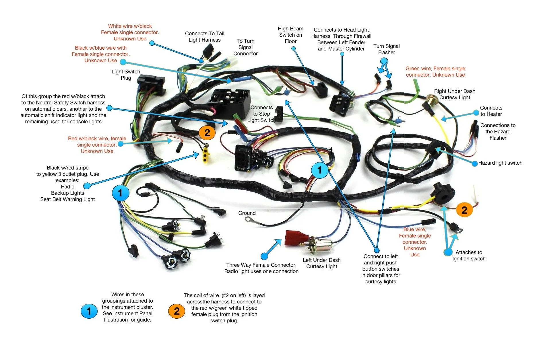
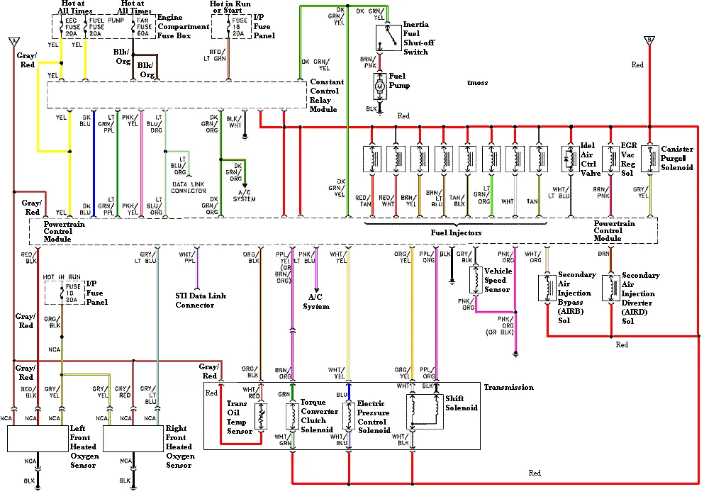
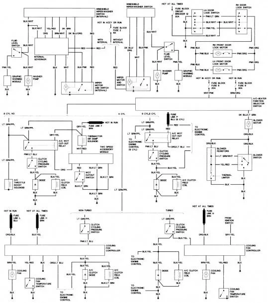
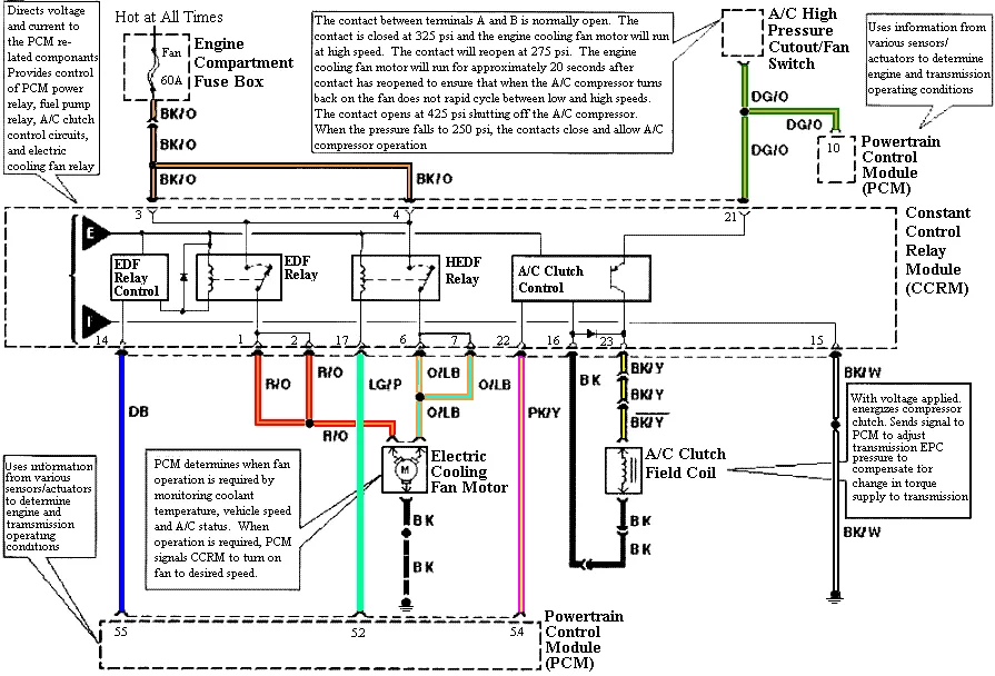
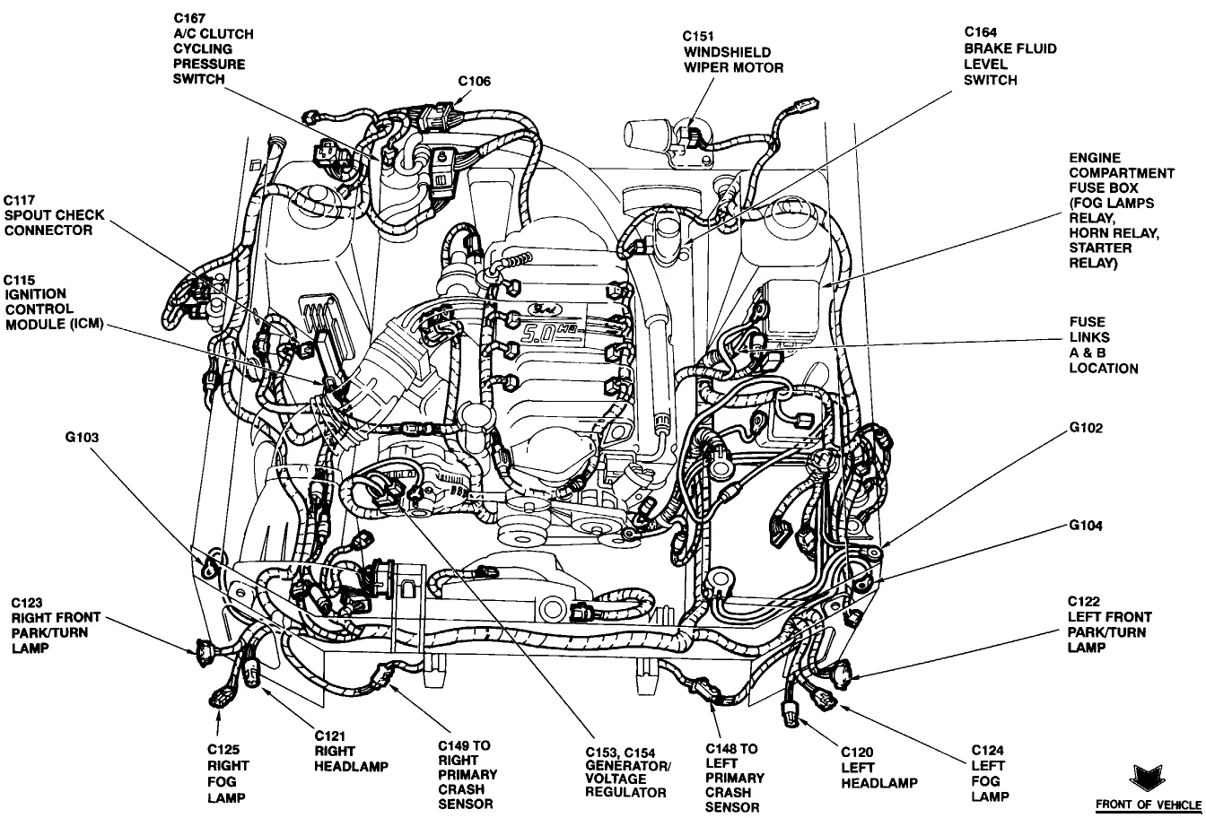
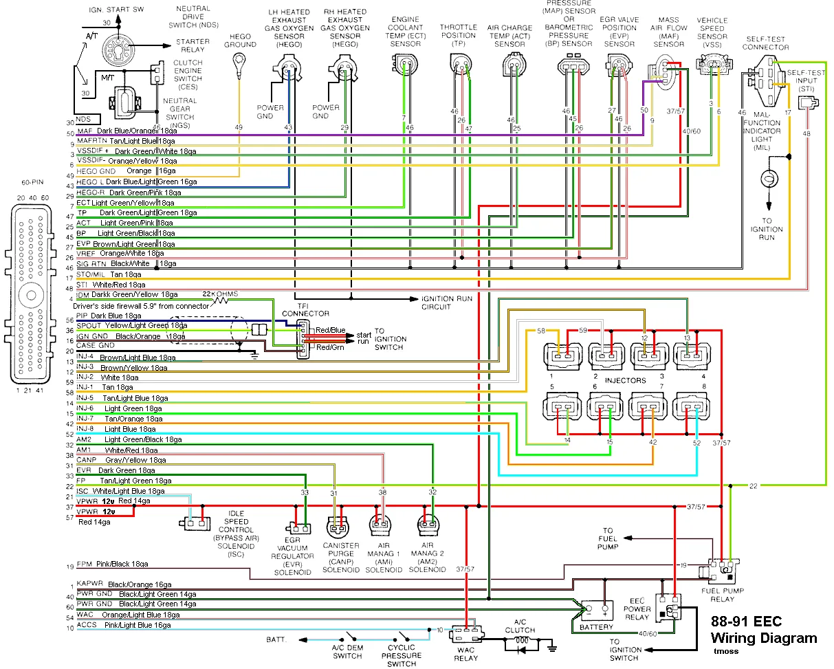
The wiring diagram for a 94 Mustang GT is divided into various sections, including engine management, fuel injection, charging system, lighting system, and much more, making it a complex process to understand.
However, having a clear understanding of the wiring diagram makes it easier to troubleshoot, diagnose, and fix any issues. Here’s a breakdown of the various sections of the wiring diagram.
Engine Management
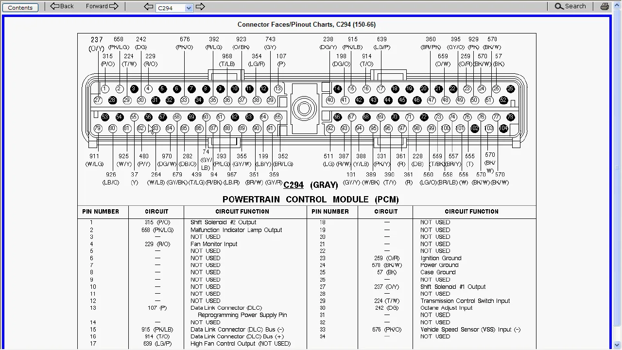
The engine management section of the wiring diagram comprises the engine control module (ECM) and the sensors that measure various engine parameters such as air volume, temperature, and pressure.
It also includes the injectors, ignition system, and the powertrain control module (PCM). Understanding this section of the wiring diagram is crucial to diagnose and fix any engine-related issues.
In addition, it’s important to note that there are various engine options available for the 94 Mustang GT, each with its own unique wiring diagram.
Fuel Injection
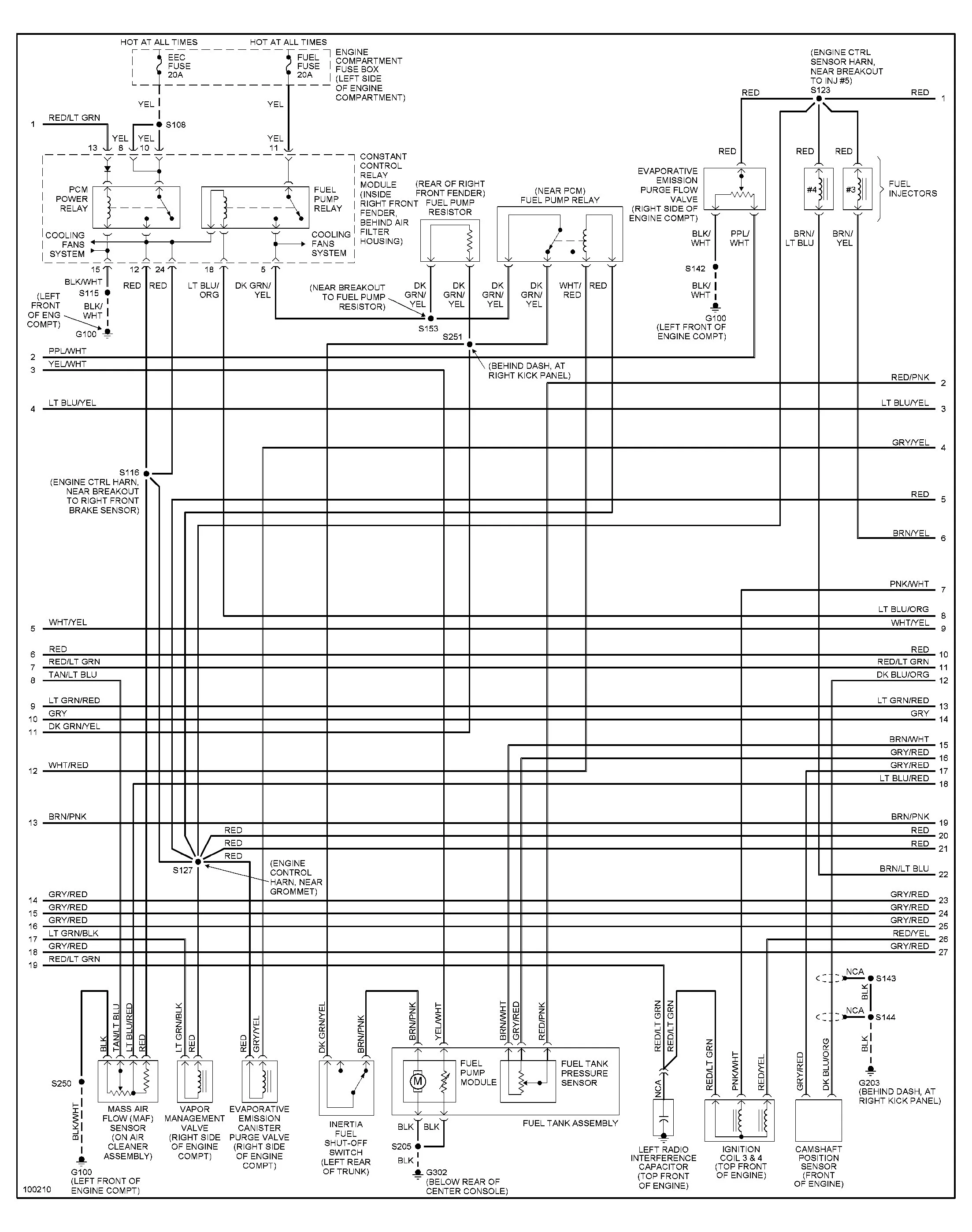
The fuel injection section of the wiring diagram includes the fuel pump, fuel injectors, fuel pressure regulator, and other components that regulate fuel delivery to the engine.
Understanding this section is crucial, especially if you’re experiencing issues with your fuel delivery system, such as low fuel pressure or fuel leaks.
Charging System
The charging system section of the wiring diagram comprises the alternator, battery, voltage regulator, and other components that regulate electrical power to the engine and other electrical systems in the car.
Understanding this section is important to ensure that your Mustang GT maintains proper voltage levels and doesn’t experience issues such as a dead battery or alternator failure.
Common Wiring Issues
Now that you have a general understanding of the various sections of the wiring diagram, let’s take a look at some common wiring issues that you may experience in your 94 Mustang GT.
Failed Sensors
One of the most common wiring issues in the engine management section of the wiring diagram is a failed sensor. If you’re experiencing issues such as poor engine performance, rough idling, or stalling, it could be due to a failed sensor.
To diagnose the issue, use a multimeter to check the voltage and resistance of the sensors. If a sensor is faulty, replace it to fix the issue.
Corroded Connections
Another common wiring issue is corroded connections. Corroded connections can cause issues such as poor fuel delivery or intermittent power delivery to the engine.
To fix the issue, use a wire brush to clean the connections and apply dielectric grease to prevent future corrosion.
Wiring Diagram FAQs
Question | Answer |
---|---|
Do I need special tools to understand the wiring diagram? | No, you don’t need any special tools, but a multimeter and a wiring diagram manual can be helpful in diagnosing and troubleshooting issues. |
Can I access the wiring diagram online? | Yes, you can access the wiring diagram online through various automotive websites or purchase a manual. |
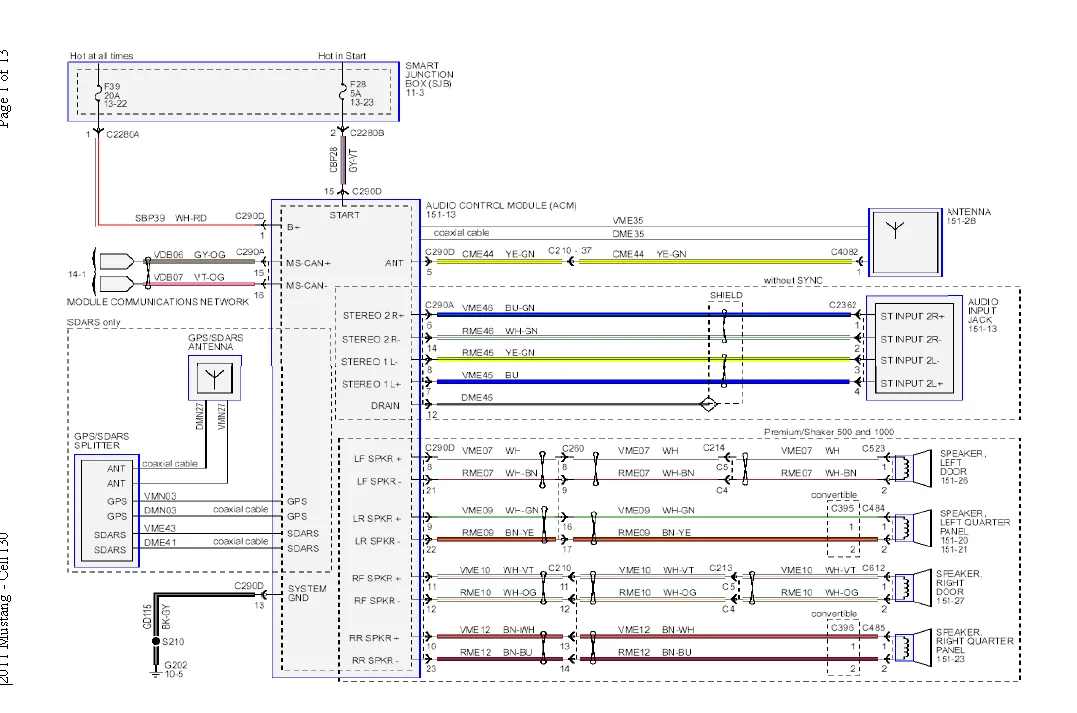
How do I read the wiring diagram? | The wiring diagram uses symbols to represent various components and connections, which are explained in the wiring diagram manual. |
Conclusion
In conclusion, understanding the wiring diagram of your 94 Mustang GT is crucial to keep it running smoothly and diagnose any issues properly. Keep in mind the various sections and common wiring issues outlined in this article, and you’ll be well on your way to fixing any wiring issues you may experience.