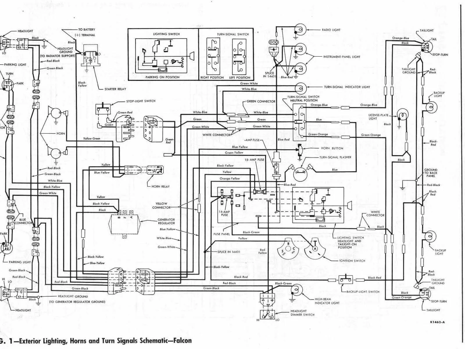
1964 Ford Galaxie Wiring Diagram

The 1964 Ford Galaxie is a classic American car that has retained its popularity among car enthusiasts for many years. This iconic vehicle is known for its elegant styling and powerful engine. However, with such a classic vehicle, comes the need for regular maintenance and repairs, including electrical wiring.

Understanding the Wiring Diagram

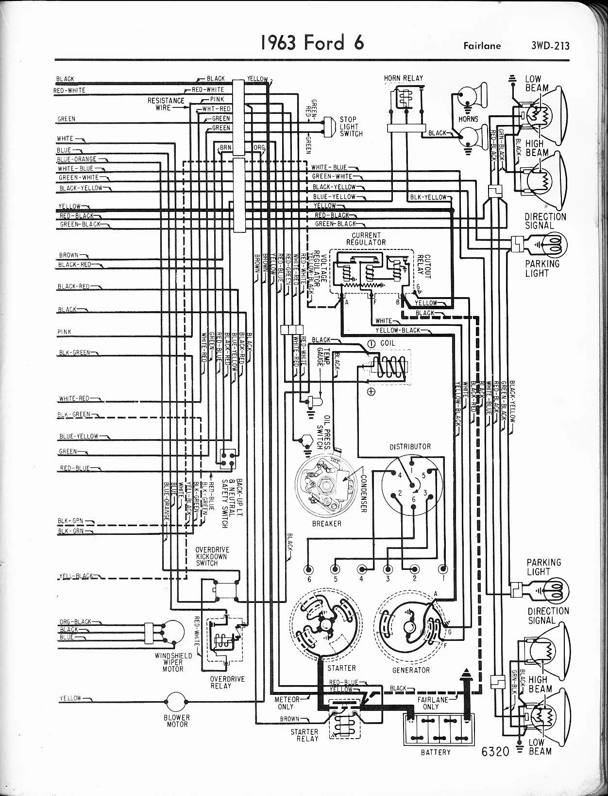
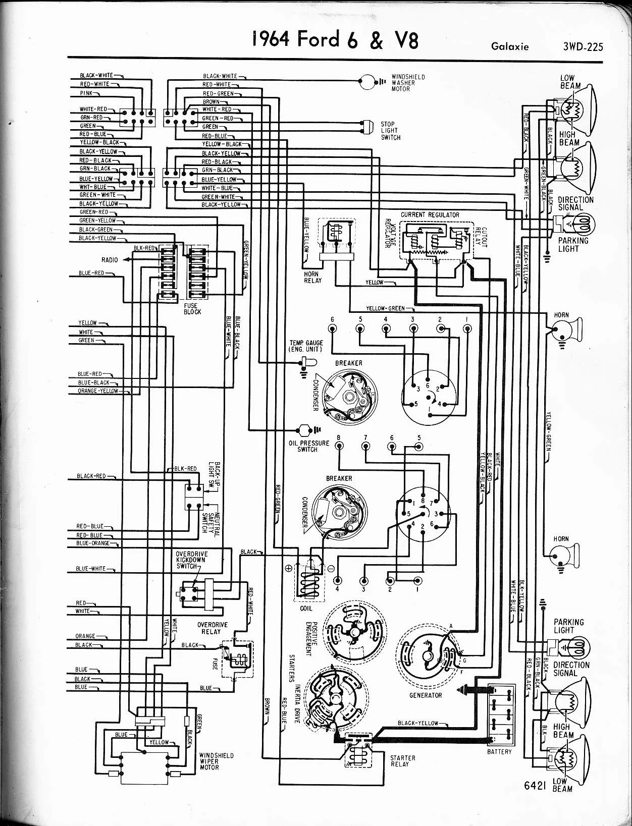
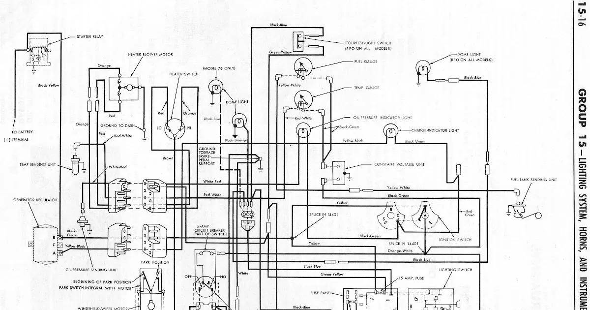
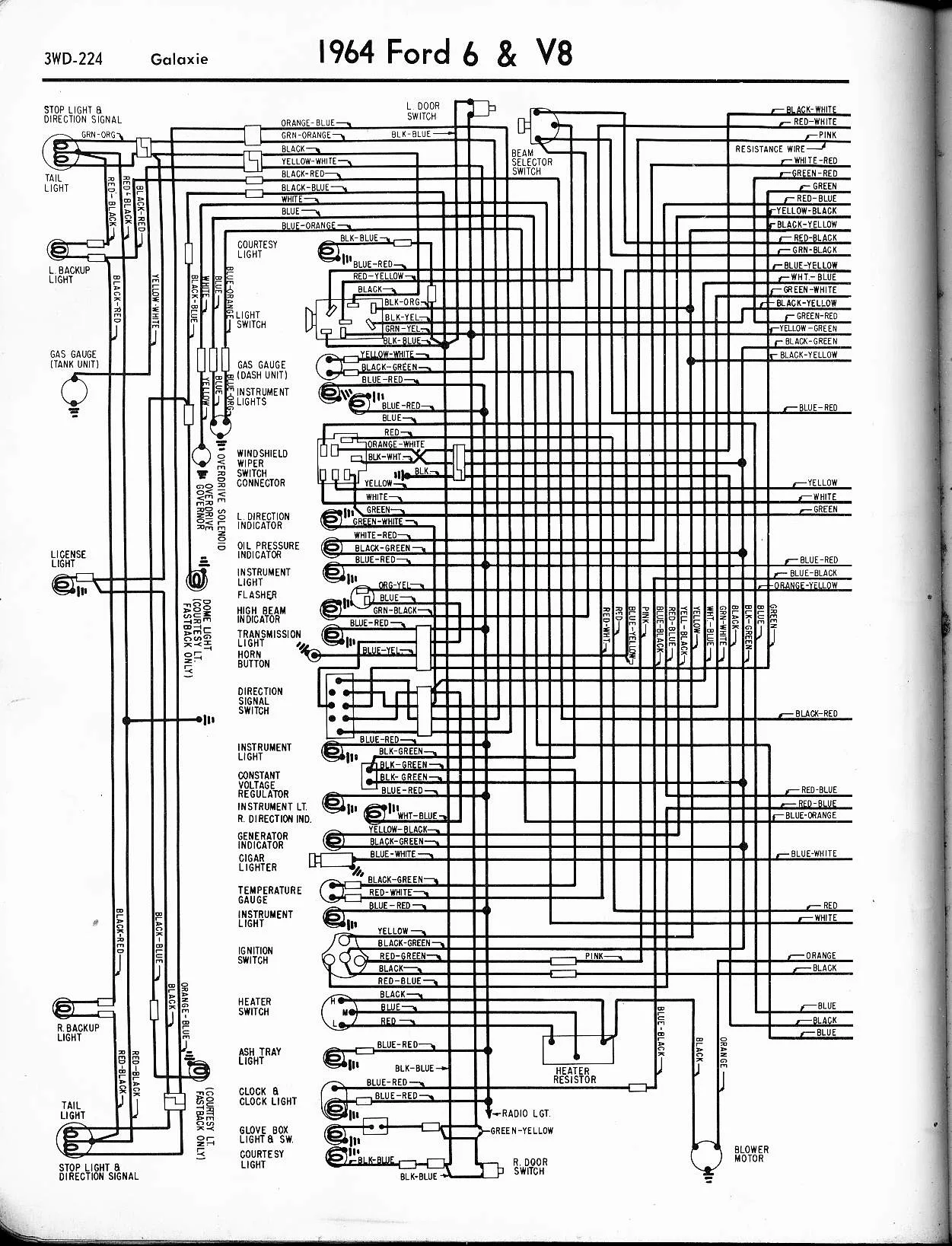
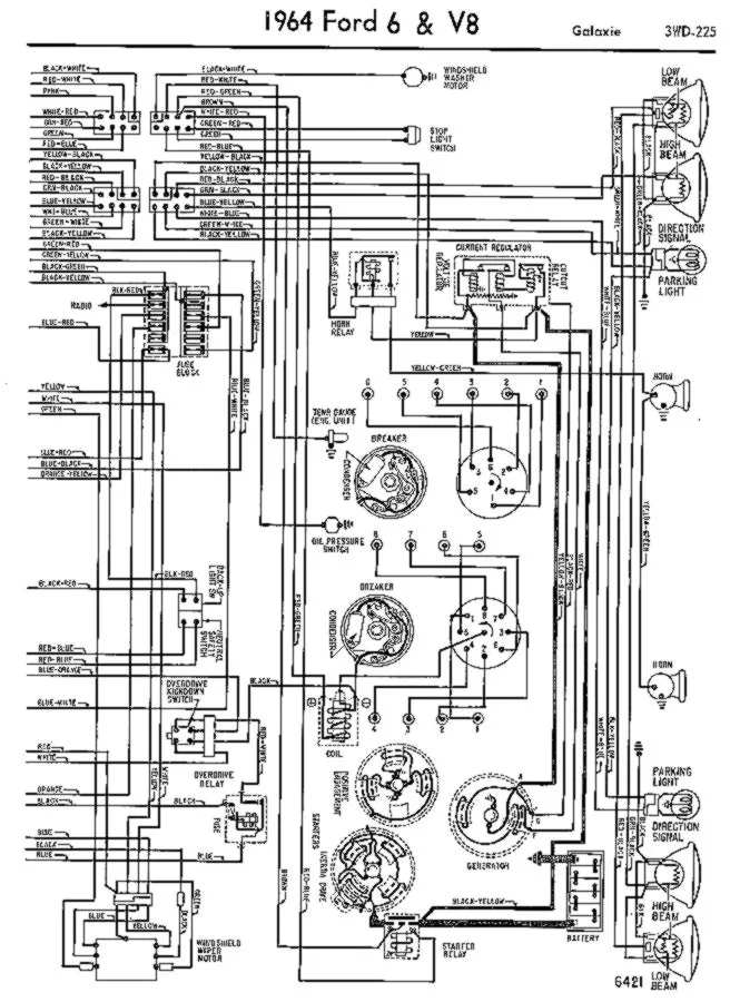
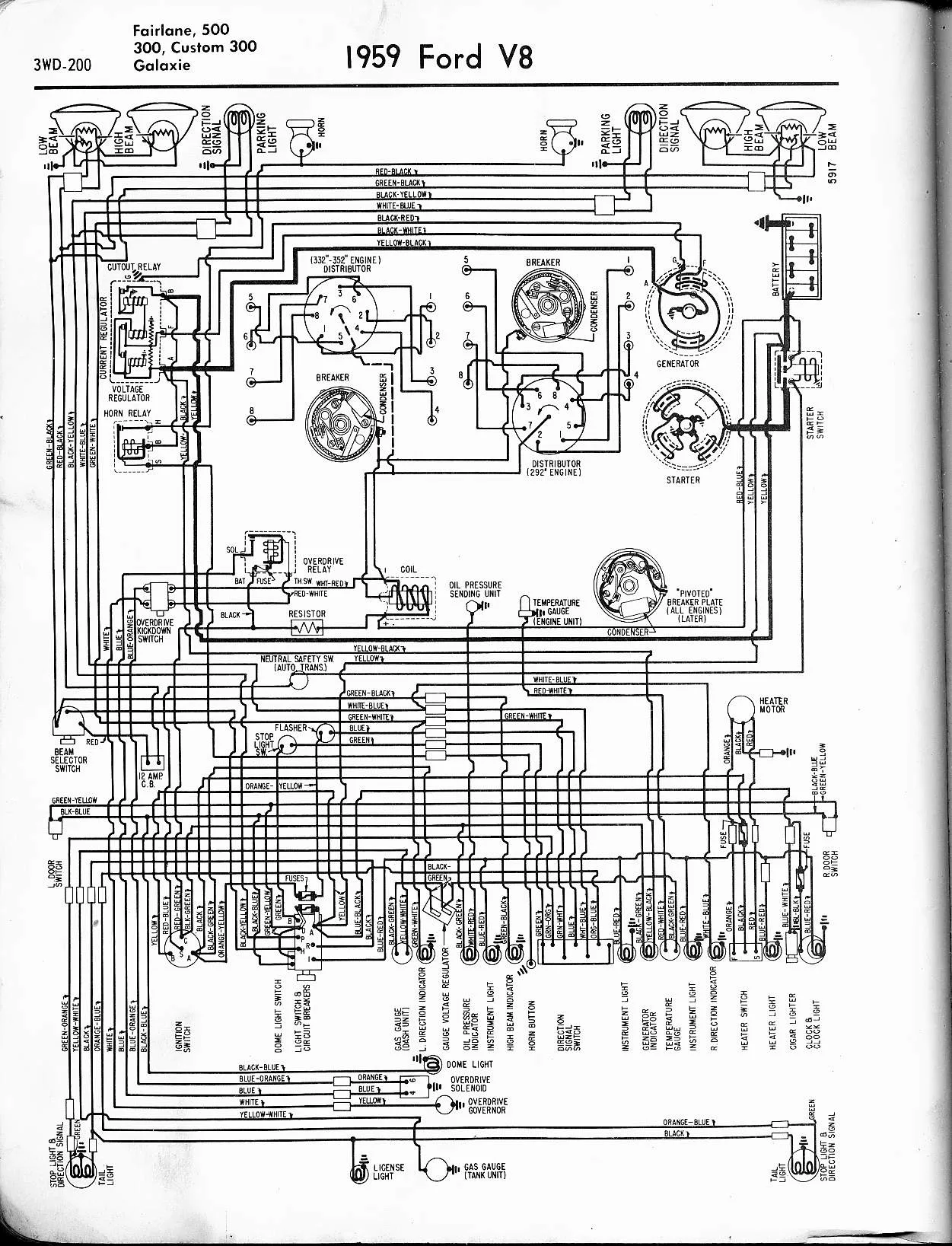
Before we dive into the specifics, it is important to understand the purpose and significance of a wiring diagram. A wiring diagram is a visual representation of the electrical system in a vehicle. It shows how various components are connected and how the electrical current flows through the system. For the 1964 Ford Galaxie, the wiring diagram is an essential tool for anyone attempting to troubleshoot or repair electrical issues.

Why is a Wiring Diagram Crucial?

A wiring diagram is crucial because it allows you to identify any potential issues before they become major problems. By having a clear visual of the electrical system, you can easily trace the flow of current and pinpoint any breaks or malfunctions. This can save you time and money in the long run.

Where to Find the Wiring Diagram?

The wiring diagram for the 1964 Ford Galaxie can be found in the vehicle’s service manual. This manual is typically available at automotive stores or can be purchased online. You can also find the wiring diagram on various websites that specialize in classic car information.

Understanding the Diagram

The wiring diagram for the 1964 Ford Galaxie can be intimidating at first glance. However, with a little bit of knowledge and patience, it is possible to understand and navigate the diagram. The diagram is broken down into various sections, including the engine compartment, instrument panel area, and rear of the car.

Each section contains various wires, connectors, and components. Understanding how each component interacts with the others is key to successfully navigating the wiring diagram.

Engine Compartment Wiring Diagram

The engine compartment wiring diagram is a crucial section of the overall wiring diagram for the 1964 Ford Galaxie. This section includes the wiring diagram for the starter, ignition, and charging systems.

Starter System Wiring

The starter system wiring diagram shows how the battery, starter solenoid, and starter motor are connected. It also shows the various wires that lead to and from the starter system.

Ignition System Wiring

The ignition system wiring diagram shows how the battery, ignition switch, and coil are connected. It also shows the various wires that lead to and from the ignition system.

Charging System Wiring

The charging system wiring diagram shows how the battery, alternator, and voltage regulator are connected. It also shows the various wires that lead to and from the charging system.

Instrument Panel Wiring Diagram

The instrument panel wiring diagram is another important section of the overall wiring diagram for the 1964 Ford Galaxie. This section includes the wiring diagram for the dashboard gauges, lights, and controls.

Gauges Wiring

The gauges wiring diagram shows how the various gauges on the dashboard are connected. It also shows the various wires that lead to and from the gauges.

Lights Wiring

The lights wiring diagram shows how the various lights on the dashboard, including the headlight switch and turn signal switch, are connected. It also shows the various wires that lead to and from the lights.

Controls Wiring

The controls wiring diagram shows how the various controls on the dashboard, including the heater switch and radio, are connected. It also shows the various wires that lead to and from the controls.

Rear Wiring Diagram

The rear wiring diagram is the final section of the overall wiring diagram for the 1964 Ford Galaxie. This section includes the wiring diagram for the tail lights, brake lights, and turn signals.

Tail Lights Wiring

The tail lights wiring diagram shows how the various wires leading to and from the tail lights are connected. It also shows how the various wires interact with the brake lights and turn signals.

Brake Lights Wiring

The brake lights wiring diagram shows how the various wires leading to and from the brake lights are connected. It also shows how the various wires interact with the tail lights and turn signals.

Turn Signals Wiring

The turn signals wiring diagram shows how the various wires leading to and from the turn signals are connected. It also shows how the various wires interact with the tail lights and brake lights.

FAQs

Question Answer
What is a wiring diagram? A wiring diagram is a visual representation of the electrical system in a vehicle.
Why is a wiring diagram important? A wiring diagram allows you to identify potential electrical issues before they become major problems.
Where can I find the wiring diagram for the 1964 Ford Galaxie? The wiring diagram can be found in the vehicle’s service manual or on various websites that specialize in classic car information.
How do I navigate the wiring diagram? Understanding how each component interacts with the others is key to successfully navigating the wiring diagram.
What does the engine compartment wiring diagram include? The engine compartment wiring diagram includes the wiring diagram for the starter, ignition, and charging systems.
What does the instrument panel wiring diagram include? The instrument panel wiring diagram includes the wiring diagram for the dashboard gauges, lights, and controls.
What does the rear wiring diagram include? The rear wiring diagram includes the wiring diagram for the tail lights, brake lights, and turn signals.

In conclusion, the wiring diagram for the 1964 Ford Galaxie is an essential tool for anyone attempting to troubleshoot or repair electrical issues. By understanding the purpose and significance of the wiring diagram, as well as each section of the diagram, you can easily identify and address any potential electrical issues. With a little bit of knowledge and patience, you can keep your classic car running smoothly for years to come.