12v Relay Wire Diagram

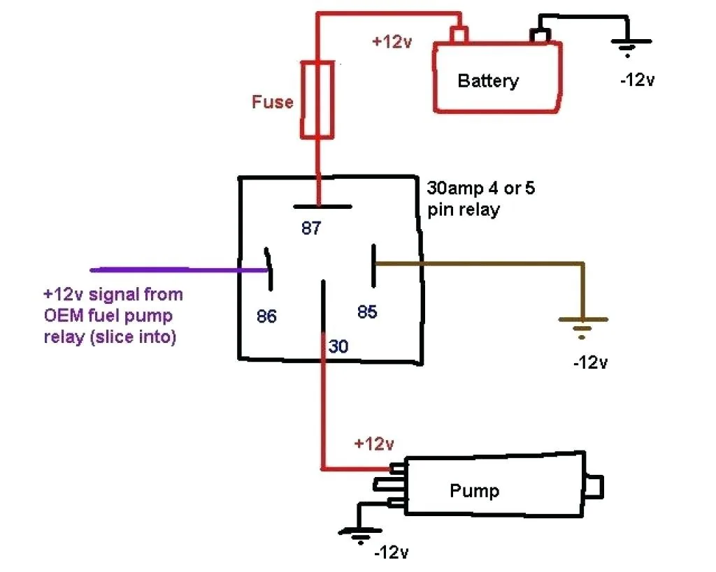
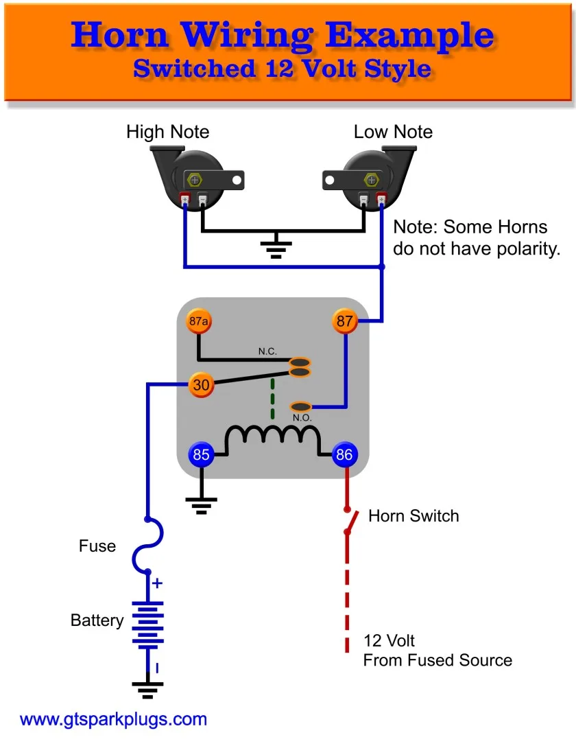
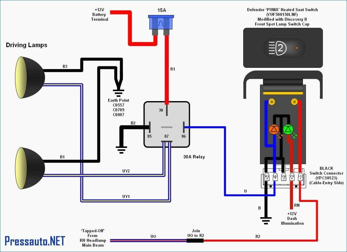
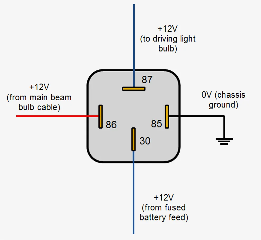
Relays are commonly used in a wide range of electrical applications, from simple electronic circuits to complex machinery. A 12v relay wire diagram is a visual depiction of how the circuit of the relay is wired. In this article, we will discuss the basics of a 12v relay wire diagram and provide some useful tips for creating and interpreting them.

What is a Relay?

Before we dive into the details of a 12v relay wire diagram, it’s important to understand what a relay is and how it works. A relay is an electromagnetic switch that opens and closes a circuit. It’s a switch that is controlled by electricity, rather than being manually operated. A relay consists of an electromagnet, a set of contacts, and a spring-loaded armature that moves when the coil is energized. When the coil is not energized, the contacts are open, and the circuit is broken. When the coil is energized, the contacts close, and the circuit is completed.

Relays are used for a variety of purposes, such as controlling lights, motors, and other electrical devices. They’re also used to protect circuits from overloading and to switch circuits on and off remotely.

How to Read a 12v Relay Wire Diagram?

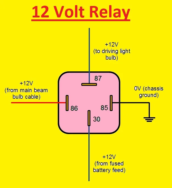
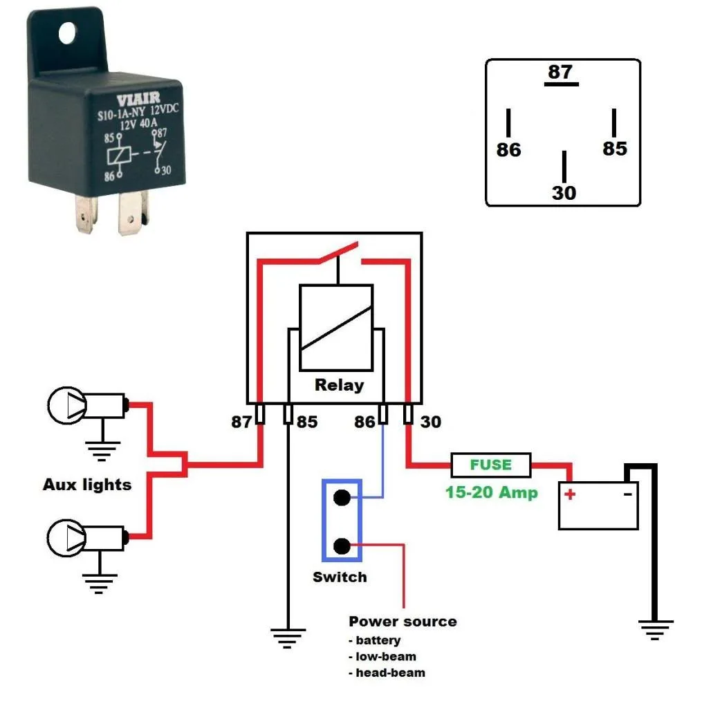
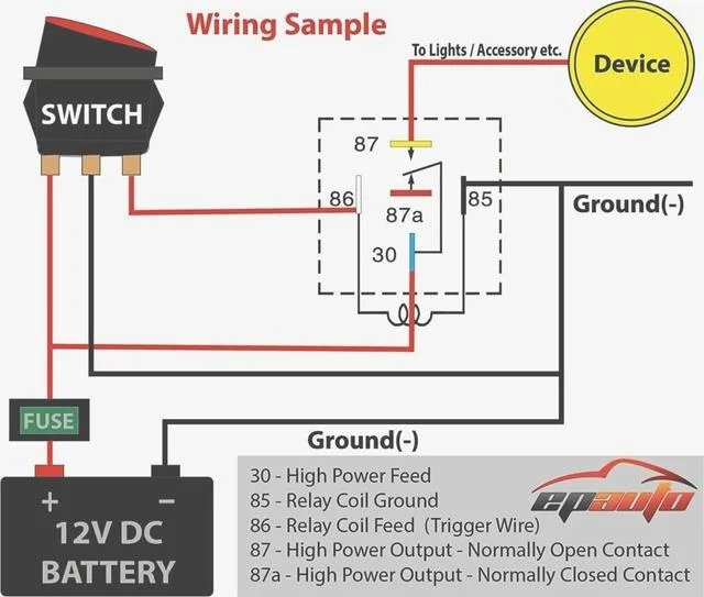
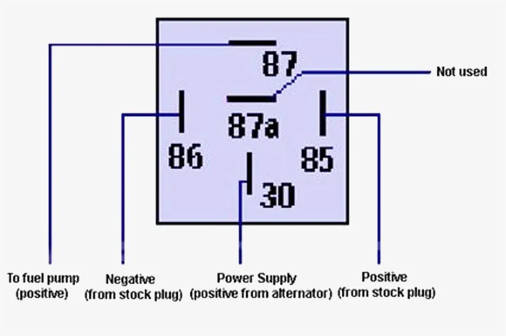
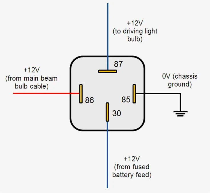
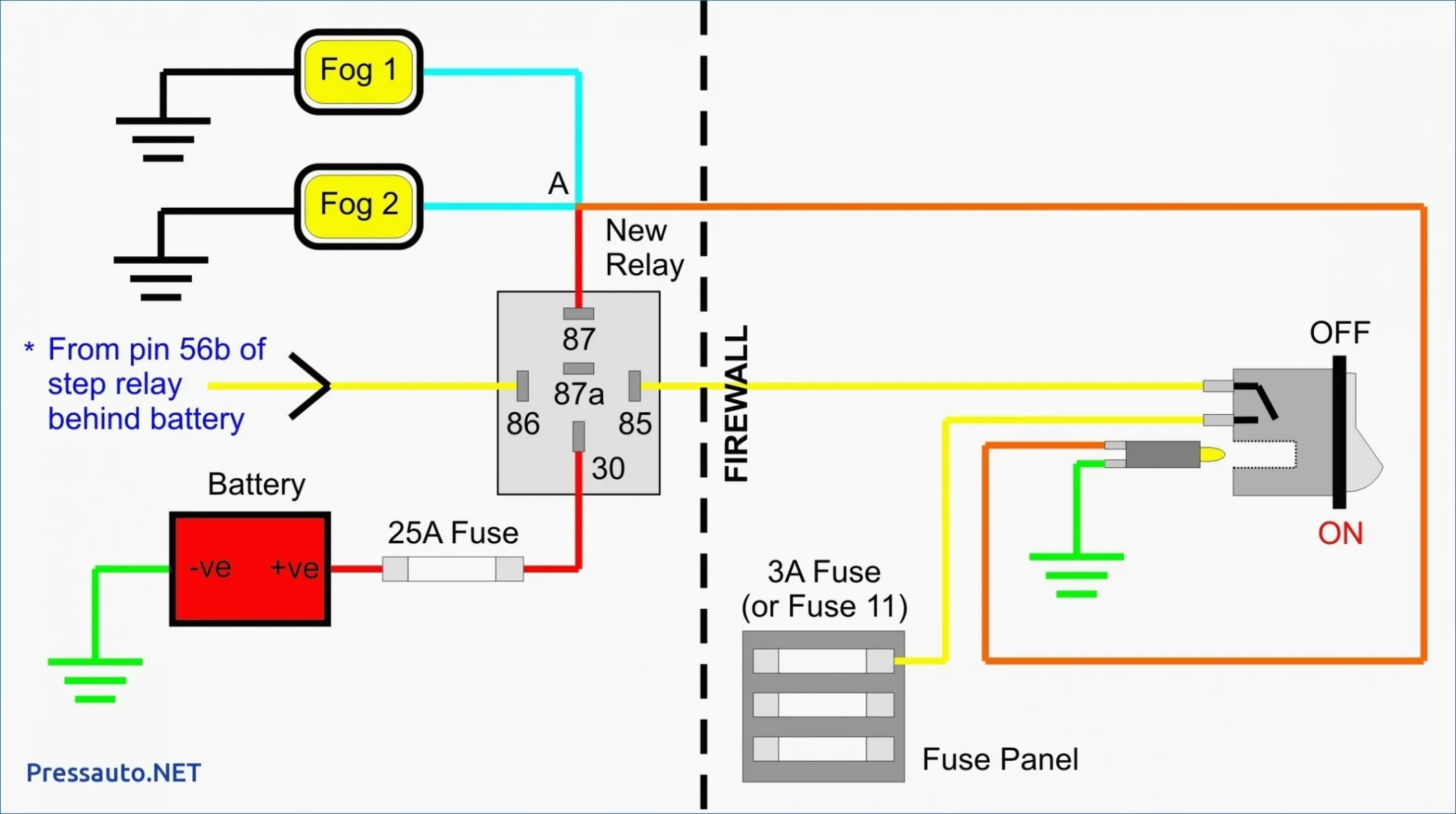
A 12v relay wire diagram is a visual representation of how the relay is wired. It shows the connections between the coil, the contacts, and any other components in the circuit. Reading a 12v relay wire diagram can be intimidating at first, but it’s actually quite simple once you know what all the symbols and lines mean.

The coil is typically shown as a circle with a “+-” sign inside it, indicating that it’s polarity sensitive. The contacts are shown as two lines that touch or cross, indicating that they’re either normally open or normally closed. The lines between the symbols represent the wires in the circuit.

When interpreting a 12v relay wire diagram, it’s important to pay attention to the position of the contacts. If the contacts are normally open, they will close when the coil is energized. If the contacts are normally closed, they will open when the coil is energized.

Basic 12v Relay Wire Diagram

A basic 12v relay wire diagram consists of a coil, a set of normally open (NO) contacts, and a set of normally closed (NC) contacts. When the coil is not energized, the NO contacts are open and the NC contacts are closed. When the coil is energized, the NO contacts close and the NC contacts open.

Table 1: Basic 12v Relay Wire Diagram

Symbol Description
+ Positive terminal
Negative terminal
Coil Electromagnet
NO Normally open contacts
NC Normally closed contacts

Advanced 12v Relay Wire Diagram

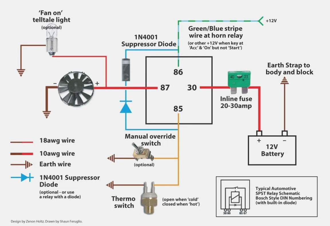
An advanced 12v relay wire diagram may include multiple coils, sets of contacts, and other components. For example, a relay used in an automotive application may include a diode to prevent voltage spikes, or a resistor to reduce current flow.

Table 2: Advanced 12v Relay Wire Diagram Components

Symbol Description
Diode Protects against voltage spikes
Resistor Reduces current flow
SPDT Single Pole Double Throw contacts
DPDT Double Pole Double Throw contacts

Frequently Asked Questions

What is the purpose of a diode in a 12v relay wire diagram?

A diode is used in a 12v relay wire diagram to protect the circuit from voltage spikes. When a relay coil is de-energized, the magnetic field collapses, which can cause a voltage spike that could damage other components in the circuit. The diode provides a path for this voltage spike to dissipate harmlessly.

What is the difference between NO and NC contacts in a 12v relay wire diagram?

NO contacts in a 12v relay wire diagram are normally open, which means they are closed only when the coil is energized. NC contacts are normally closed, which means they are open only when the coil is energized.

How do I know if a 12v relay wire diagram is correct?

A 12v relay wire diagram is correct if it represents the actual circuit as it is wired. To verify that the diagram is correct, you can use a multimeter to check the continuity of the wires and the position of the contacts.

What is the maximum current that a 12v relay can handle?

The maximum current that a 12v relay can handle depends on the specific relay and its specifications. It’s important to consult the manufacturer’s datasheet to determine the maximum current rating.

Can a 12v relay be used in a 24v circuit?

Some 12v relays can be used in a 24v circuit, but it’s important to check the manufacturer’s specifications to make sure. Using a relay in a circuit with a voltage higher than its rated voltage can cause it to fail prematurely or not function properly.

Conclusion

In conclusion, a 12v relay wire diagram is an essential tool for understanding the wiring of a relay. It’s important to know how to read these diagrams and to understand the symbols used. With the tips and information provided in this article, you should be able to create and interpret 12v relay wire diagrams with ease.