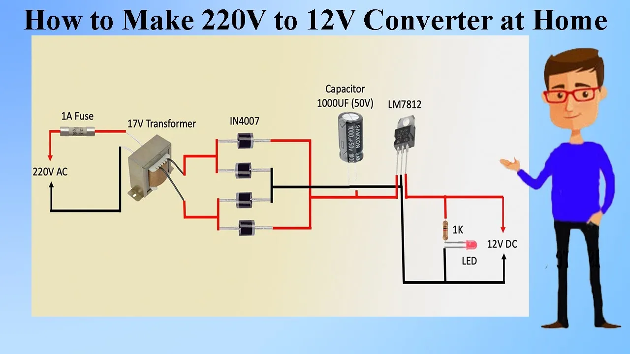
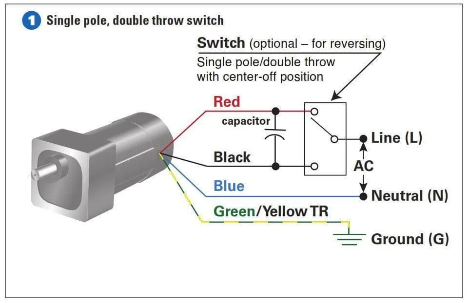
12V DC Schematic Wiring Diagram: A Comprehensive Guide

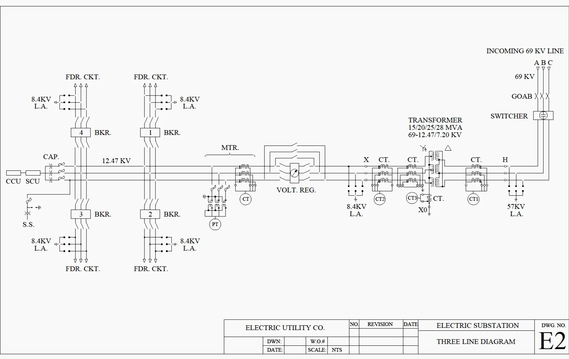
When it comes to wiring a 12V DC circuit, a schematic wiring diagram can be incredibly useful. A schematic diagram shows the electrical connections between components and illustrates how they are arranged in a circuit. In this article, we’ll walk you through the basics of creating a schematic diagram for a 12V DC circuit.

What is a 12V DC Circuit?

A 12V DC circuit is a circuit that operates on a direct current (DC) voltage of 12 volts. DC circuits are commonly used in automotive, marine, and off-grid electrical systems. In a 12V DC circuit, power is supplied from a battery or other DC power source.

DC circuits are different from alternating current (AC) circuits, which operate on a voltage that changes direction and magnitude over time.

Creating a 12V DC Schematic Wiring Diagram

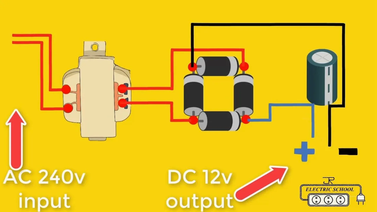
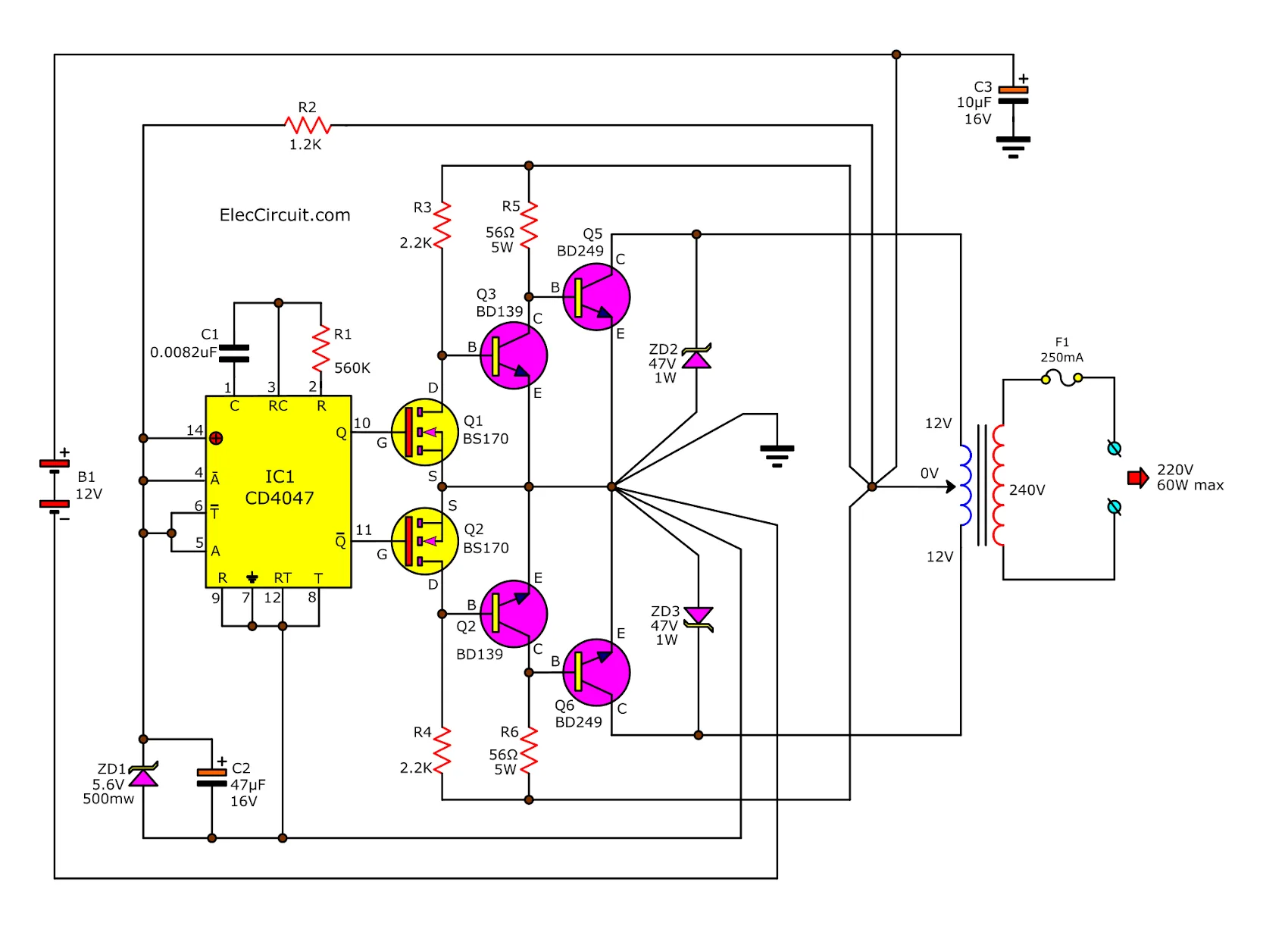
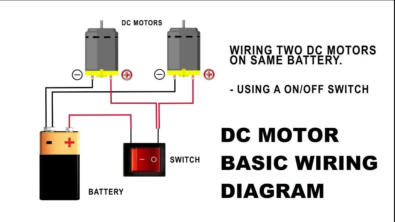
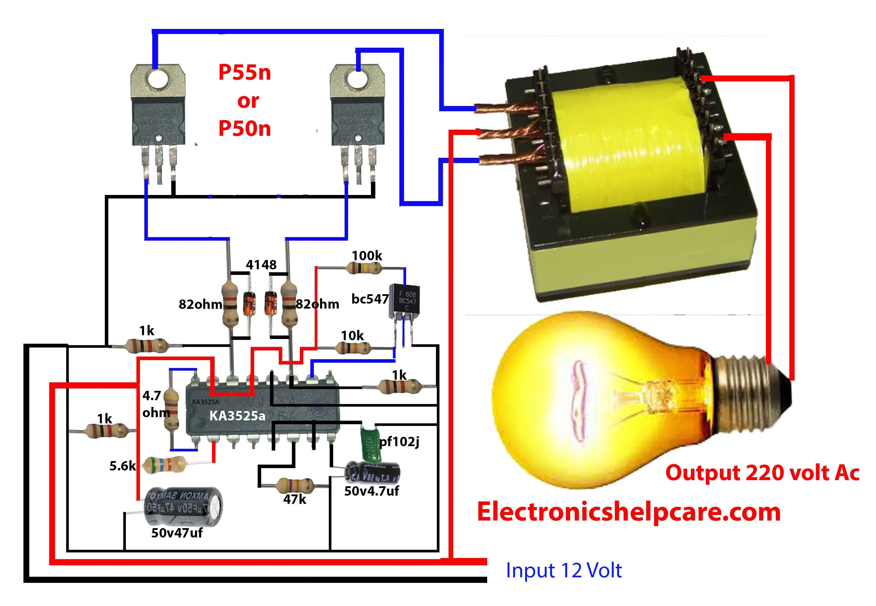
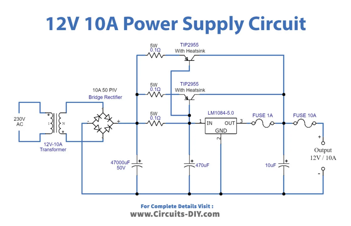
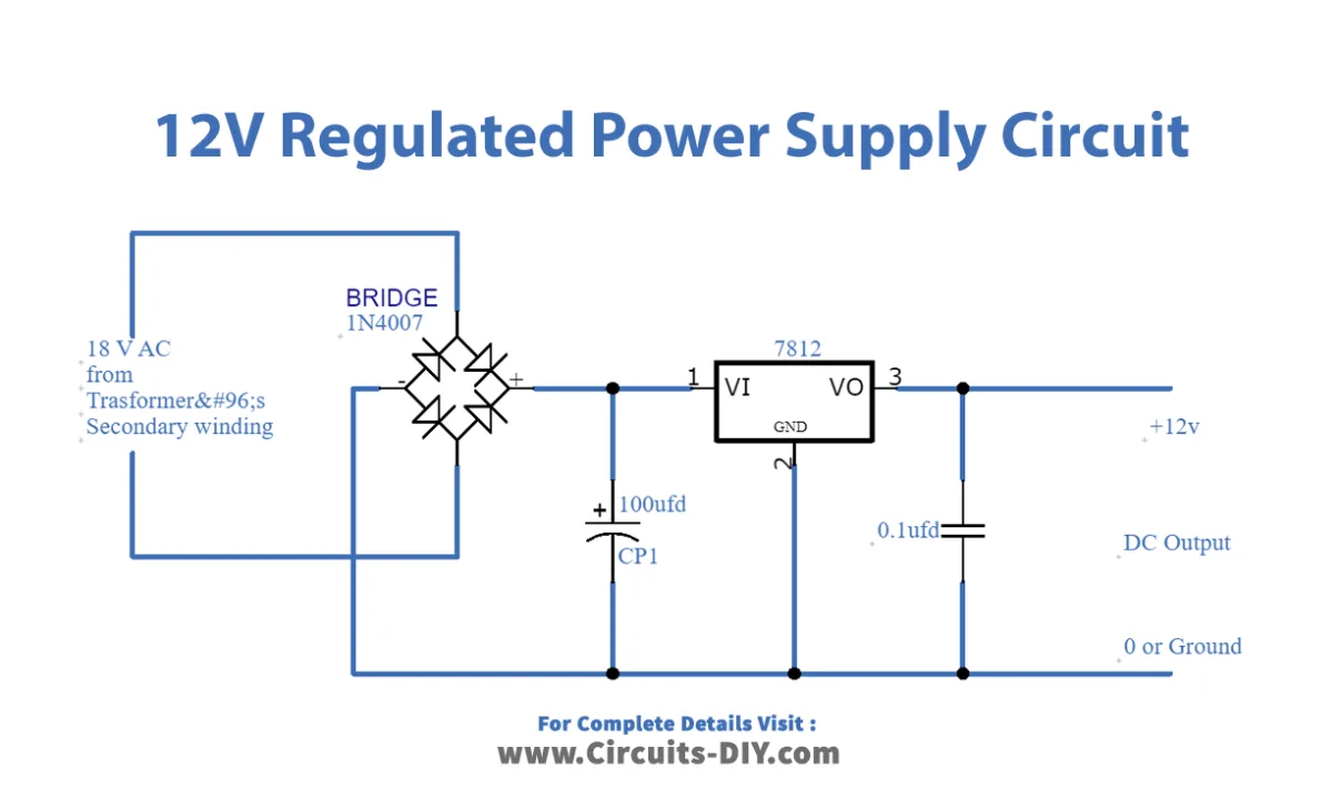
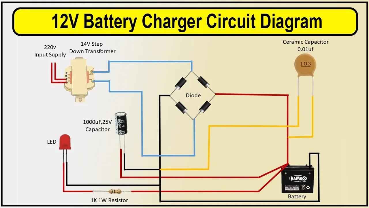
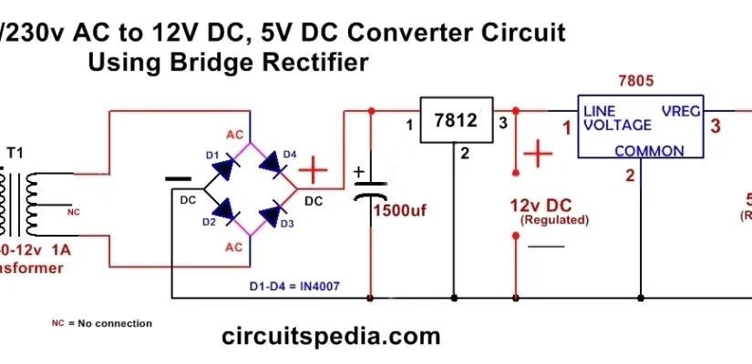
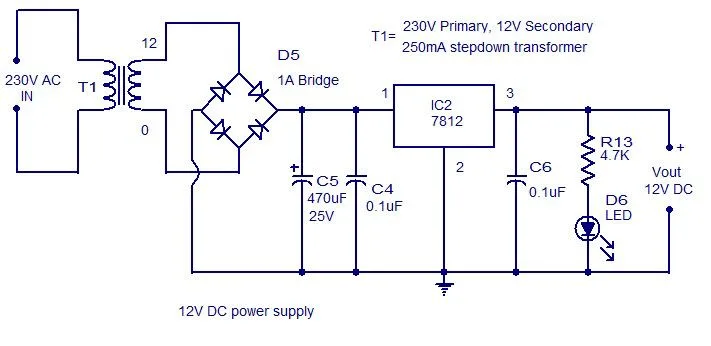
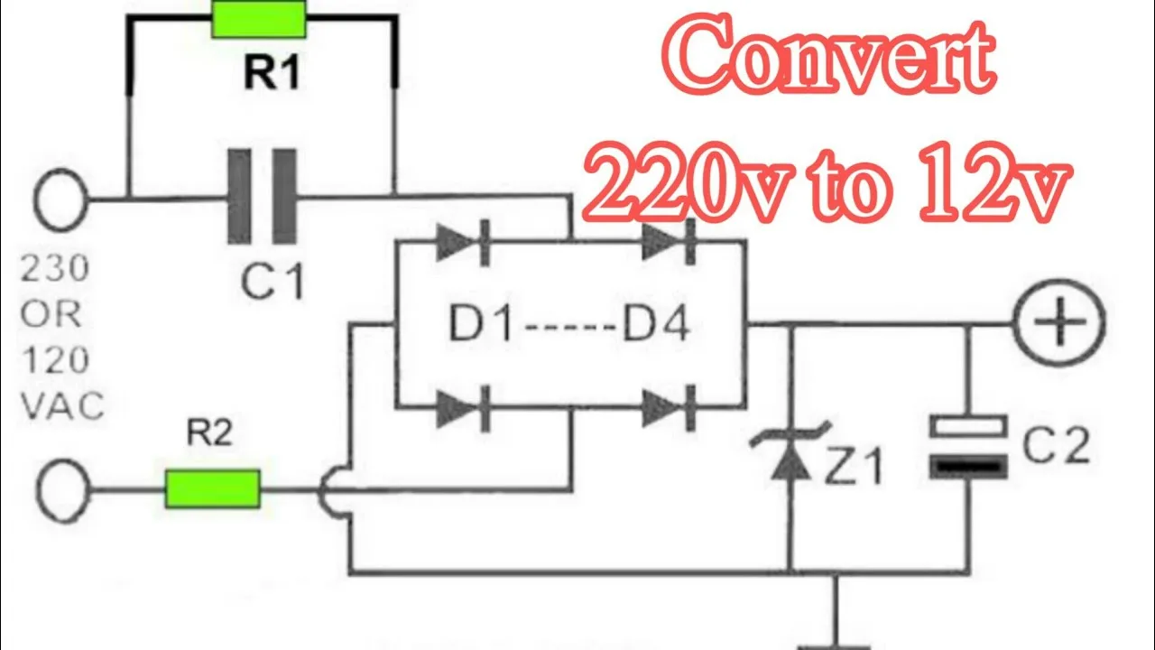
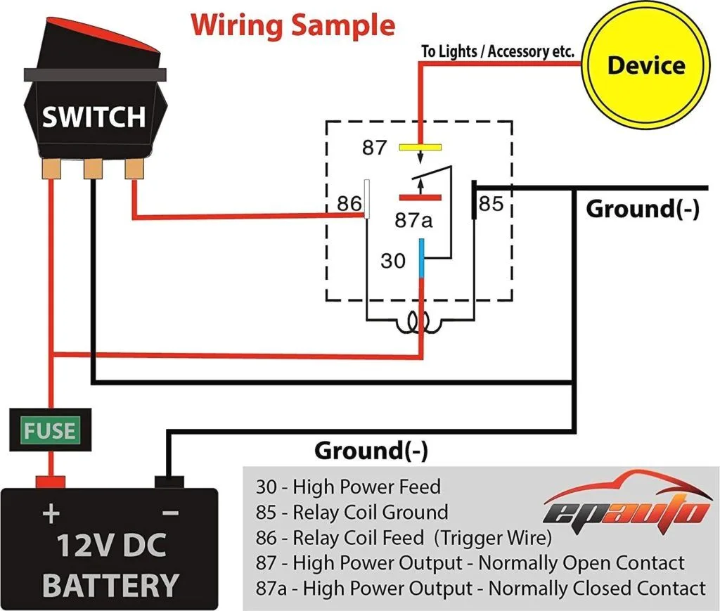
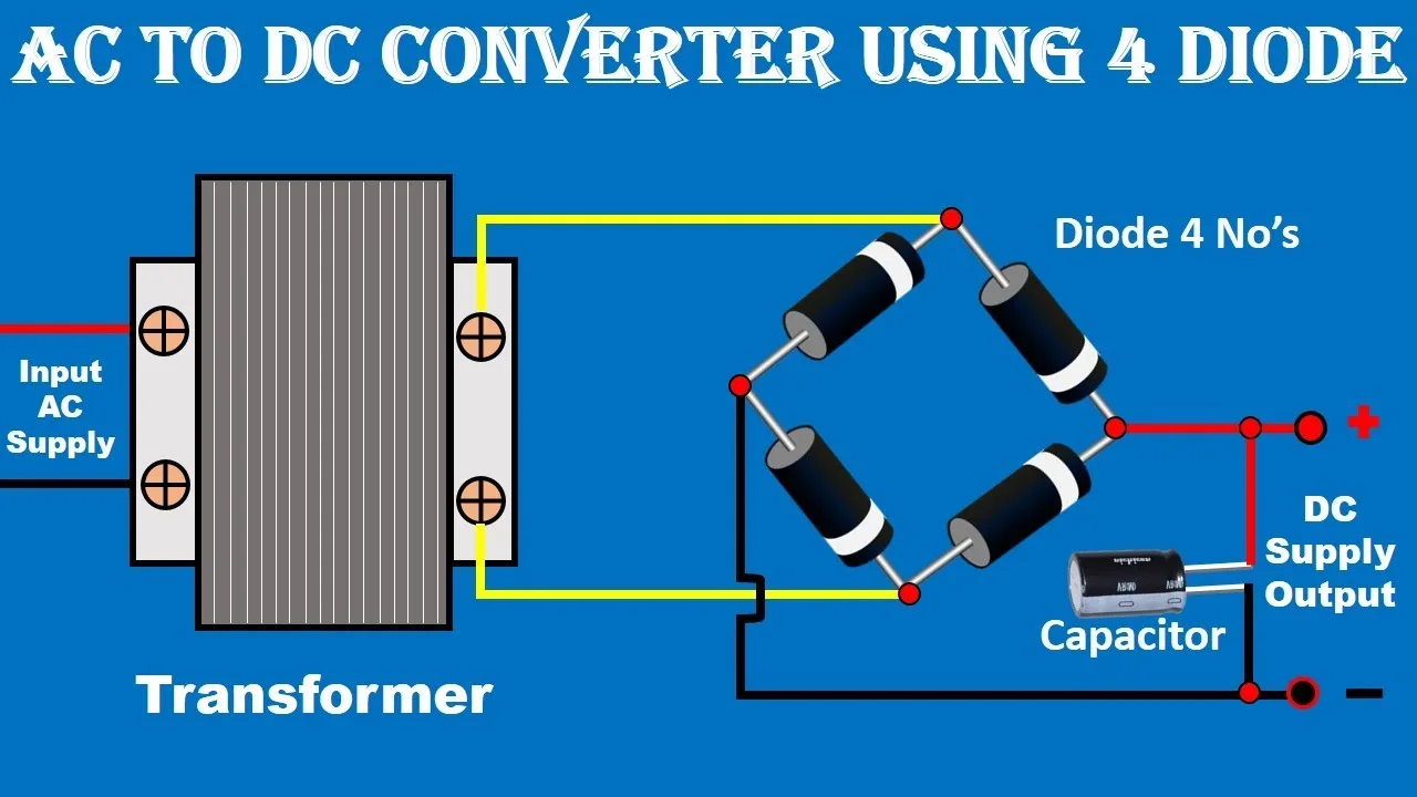
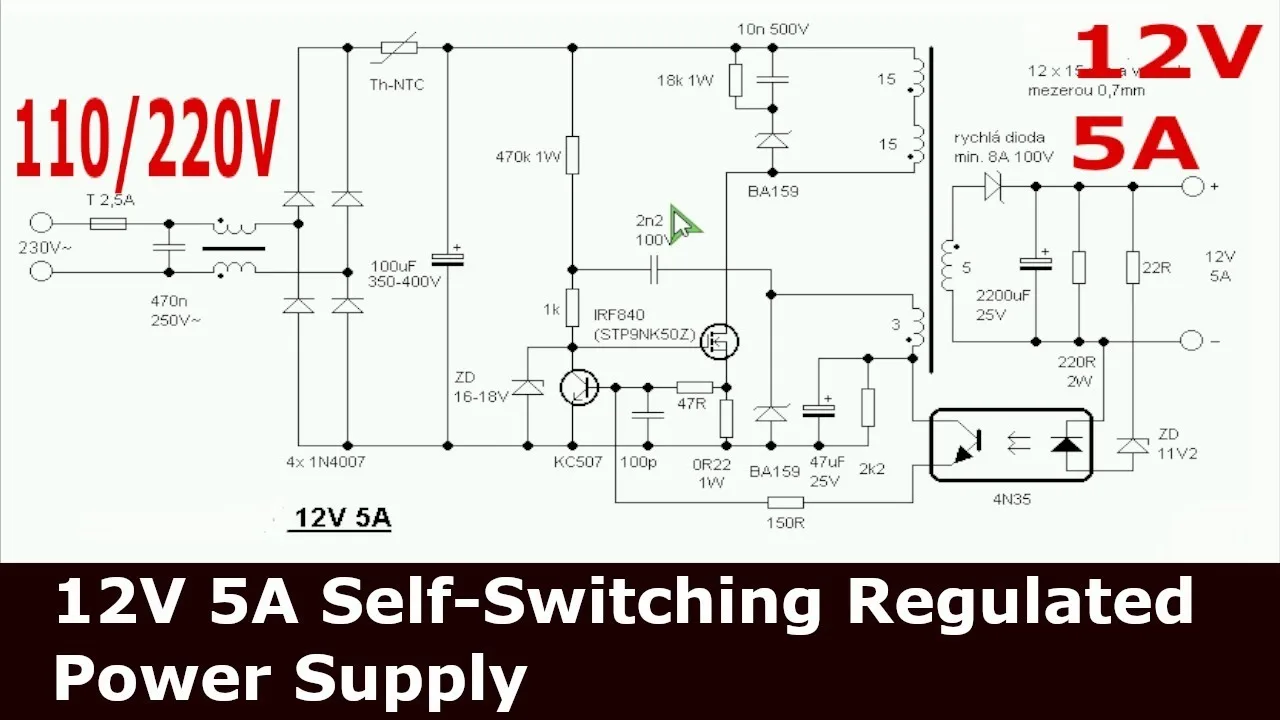
A 12V DC schematic wiring diagram is a visual representation of a circuit, showing how the components are connected together. To create a schematic diagram for a 12V DC circuit, you will need to follow these steps:

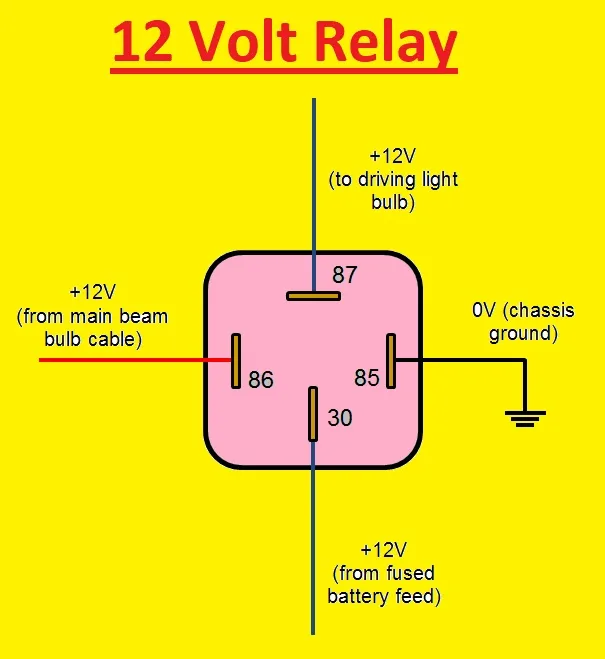
  1. Identify the components that you will use in your circuit, such as switches, fuses, relays, and wires.
  2. Determine the connections between the components, including which wires connect to which terminals and what the polarity of the connection is (positive or negative).
  3. Draw the schematic diagram using symbols to represent the components and lines to represent the connections between them.
  4. Add labels to the diagram to identify each component and its function.

Once you have created your schematic wiring diagram, you can use it to guide the actual wiring of your circuit.

Understanding 12V DC Wiring Diagram Symbols

When creating a 12V DC wiring diagram, it’s important to use the correct symbols to represent the components. Here are some of the most common symbols used in schematic diagrams:

Symbol Component
Battery A power source that supplies a constant voltage.
Switch A device that interrupts or connects a circuit.
Resistor A component that limits the flow of current in a circuit.
Capacitor A component that stores electrical energy and releases it over time.
LED A light emitting diode that converts electrical energy into light.

Other symbols include fuses, diodes, transistors, and relays, among others. It’s important to use the correct symbol for each component to avoid confusion and ensure accurate representation of the circuit.

FAQs

What is the difference between a schematic diagram and a wiring diagram?

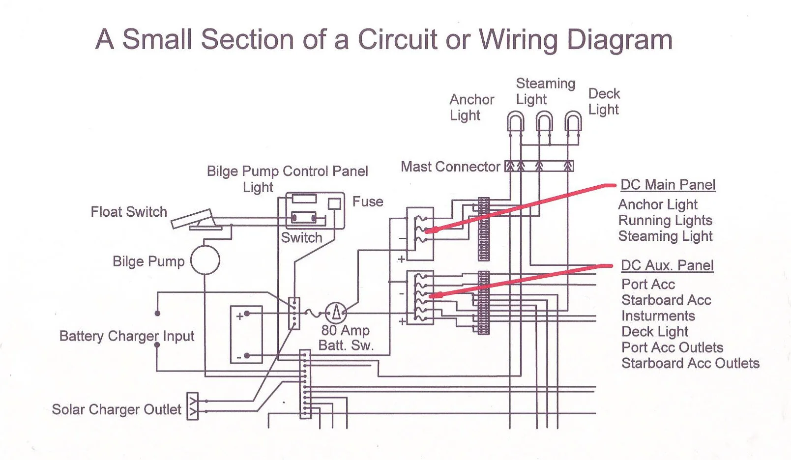
A schematic diagram shows the electrical connections between components and their arrangement in a circuit, while a wiring diagram shows the physical layout of the wires and where they connect to the components. Schematic diagrams are often used in the design and analysis of circuits, while wiring diagrams are used for installation and repair.

Why is a schematic diagram important?

A schematic diagram helps to visually represent a circuit and its components, making it easier to understand and troubleshoot. It also allows for easier modification and design of circuits, as well as documentation and communication with others.

What is the voltage of a 12V DC circuit?

A 12V DC circuit operates on a direct current voltage of 12 volts. This voltage is supplied by a battery or other DC power source.

What are some common uses for 12V DC circuits?

12V DC circuits are commonly used in automotive, marine, and off-grid electrical systems. Examples include lighting, fans, pumps, and other electrical devices that operate on a 12V DC voltage.

What is the difference between a 12V DC circuit and an AC circuit?

A 12V DC circuit operates on a direct current voltage of 12 volts, while an AC circuit operates on a voltage that changes direction and magnitude over time. AC circuits are commonly used in household electrical systems, while DC circuits are used in automotive, marine, and off-grid applications.

Conclusion

A 12V DC schematic wiring diagram is an essential tool for designing and troubleshooting electrical circuits. By following best practices for creating schematic diagrams and using correct symbols, you can create an accurate representation of your circuit that will guide your actual wiring and ensure proper operation. By understanding the basics of 12V DC circuits and wiring diagrams, you can tackle a variety of electrical projects with confidence.