110v Schematic Wiring Diagram Schematic – A Comprehensive Guide

110v Schematic Wiring Diagram Schematic – A Comprehensive Guide

When it comes to wiring schematic diagrams, it can be a daunting task for many people. However, this guide will make it easy for you to understand the 110v schematic wiring diagram schematic. This guide will cover everything from what a schematic diagram is to how to read it and much more. So, let’s dive in!

What is a Schematic Diagram?

A schematic diagram is a graphical representation of an electronic circuit. It uses symbols to represent the components of the circuit and shows how they are connected. It is a crucial aspect of any electrical or electronic circuit as it enables the technician or engineer to understand how the system works and diagnose problems. Schematic diagrams are typically used in industries such as electronics, electrical, and telecommunications.

Why is a Schematic Diagram Important?

A schematic diagram is essential as it provides information about how the electronic or electrical system is designed and how it operates. It is also useful in diagnosing problems and troubleshooting any issues that may arise. Additionally, it saves time as it helps to identify the problem quickly and allows engineers and technicians to fix the problem promptly.

What Symbols are Used in Schematic Diagrams?

There are a variety of symbols used in schematic diagrams such as resistors, capacitors, transistors, and much more. These symbols are standardized to make it easy for technicians and engineers to understand the diagram. The symbols used in a schematic diagram are usually specific to the industry, and it may be different from other industries. Therefore, it is essential to be familiar with the symbols used in your industry.

How to Read a Schematic Diagram?

Reading a schematic diagram requires understanding the symbols used and how they are connected in the circuit. The first step is to identify the power source and the ground. In most cases, the power source is located at the top of the diagram, and the ground is at the bottom. Next, identify the different components and how they are connected. Finally, trace the path of the power flow to understand how the circuit operates.

110v Schematic Wiring Diagram Schematic

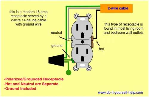
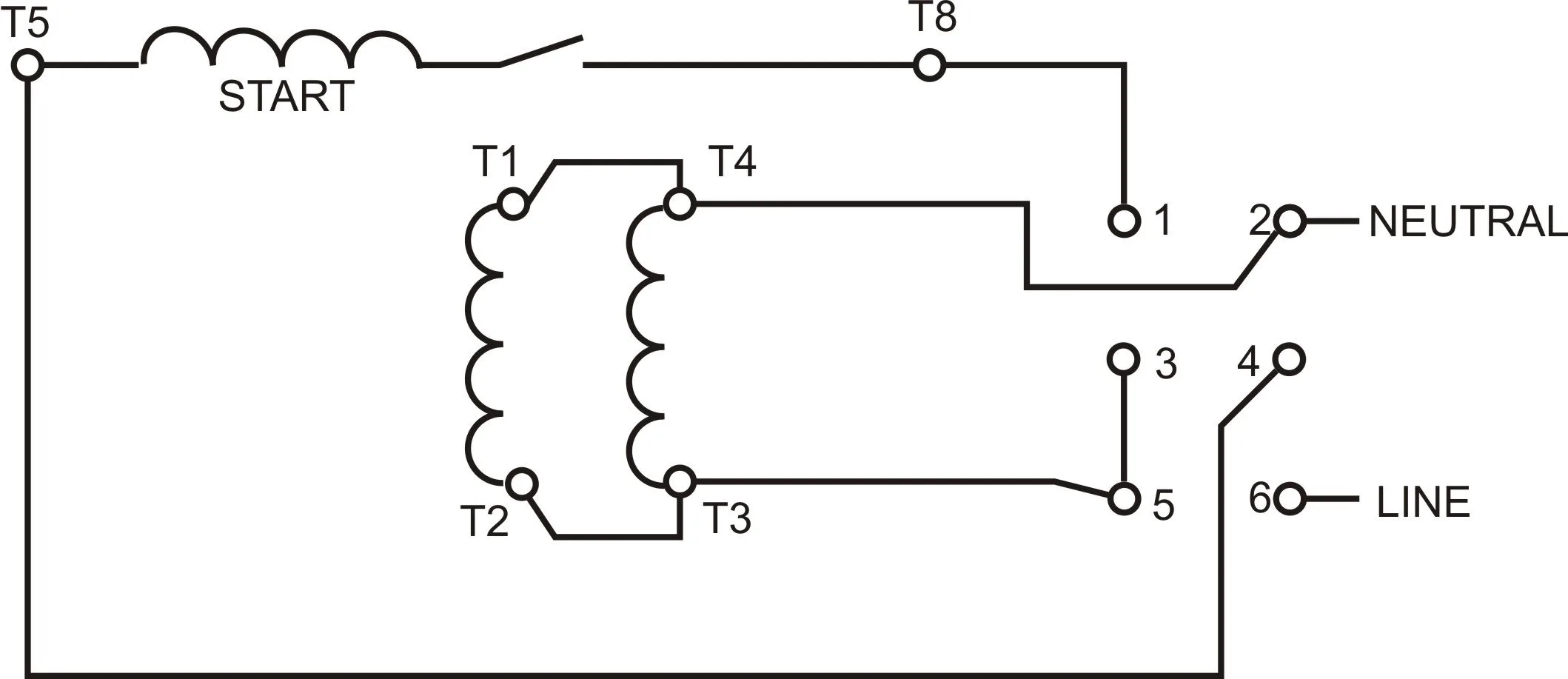
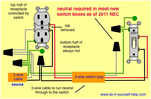
The 110v schematic wiring diagram schematic is a diagram that shows how the electrical system of a device or building is designed and wired. It uses symbols to represent the different components of the circuit and shows how they are connected. It is crucial to understand the 110v schematic wiring diagram schematic as it is commonly used in residential and commercial buildings.

What is the 110v Electrical System?

The 110v electrical system is a standard electrical system used in North America. It uses 110 volts to power devices and appliances in homes and commercial buildings. The 110v system is the most common electrical system in use in North America, and it is crucial to understand how it works to diagnose and fix any problems that may arise.

What are the Components of the 110v Electrical System?

The components of the 110v electrical system include the circuit breaker panel, wiring, outlets, switches, and appliances. The circuit breaker panel is where the power enters the building, and it is protected by circuit breakers that trip when there is a power surge or overload. The wiring connects the circuit breaker panel to the outlets, switches, and appliances. The outlets and switches provide a means for devices and appliances to be plugged in and controlled.

How to Read a 110v Schematic Wiring Diagram Schematic?

Reading a 110v schematic wiring diagram schematic requires understanding the symbols used and how they are connected. The diagram typically includes the circuit breaker panel, wiring, outlets, switches, and appliances. The first step is to identify the power source and the ground. Next, identify the different components and how they are connected. Finally, trace the path of the power flow to understand how the circuit operates.

FAQ

Question Answer
What is a 110v schematic wiring diagram schematic? A 110v schematic wiring diagram schematic is a diagram that shows how the electrical system of a device or building is designed and wired.
What are the components of the 110v electrical system? The components of the 110v electrical system include the circuit breaker panel, wiring, outlets, switches, and appliances.
How to read a 110v schematic wiring diagram schematic? Reading a 110v schematic wiring diagram schematic requires understanding the symbols used and how they are connected. The first step is to identify the power source and the ground. Next, identify the different components and how they are connected. Finally, trace the path of the power flow to understand how the circuit operates.

Conclusion

The 110v schematic wiring diagram schematic is a critical aspect of any electrical or electronic circuit. It is essential to understand the symbols used and how they are connected to diagnose and fix any problems that may arise. This guide has covered everything from what a schematic diagram is to how to read it and much more. We hope that this guide has been helpful and informative in understanding the 110v schematic wiring diagram schematic.