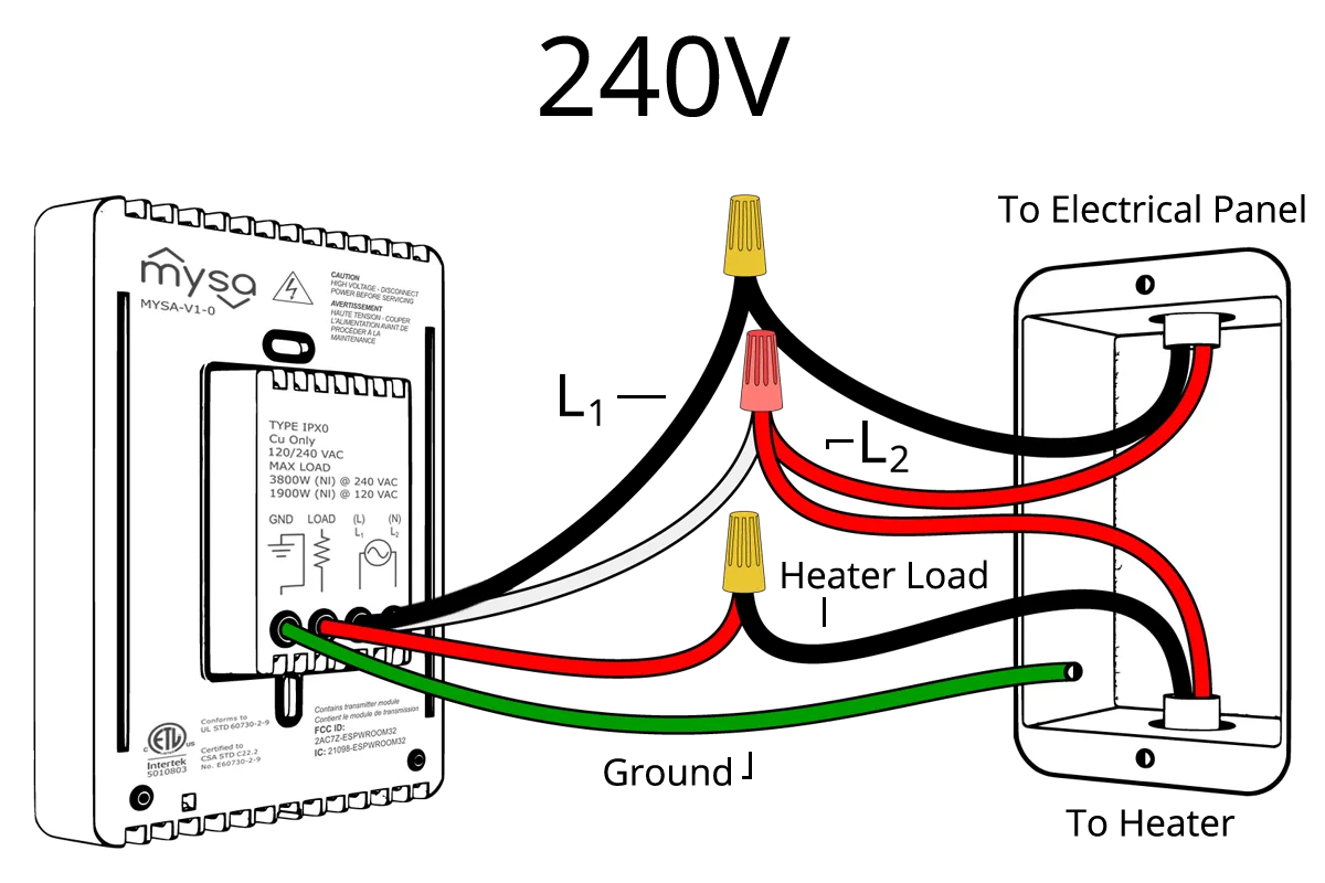
Understanding 110 Volt Wiring Diagrams

Electrical wiring is an integral part of any building or system, and it requires careful planning and execution. One of the most common types of wiring systems is the 110 volt wiring system, which is used in homes, offices, and other buildings. In this article, we will discuss the basics of 110 volt wiring diagrams, their applications, and how to create them in a simplified and understandable manner.

What is a 110 Volt Wiring Diagram?

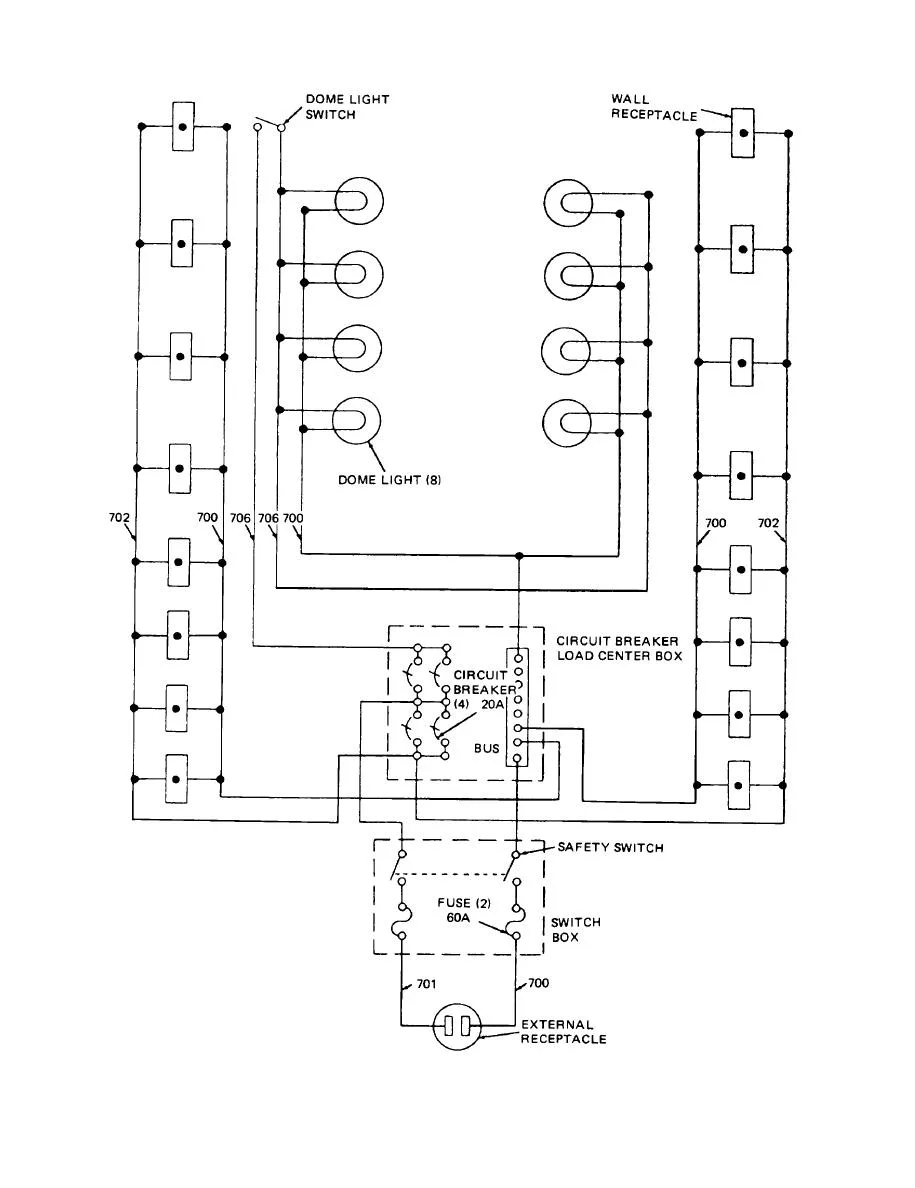
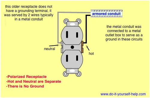
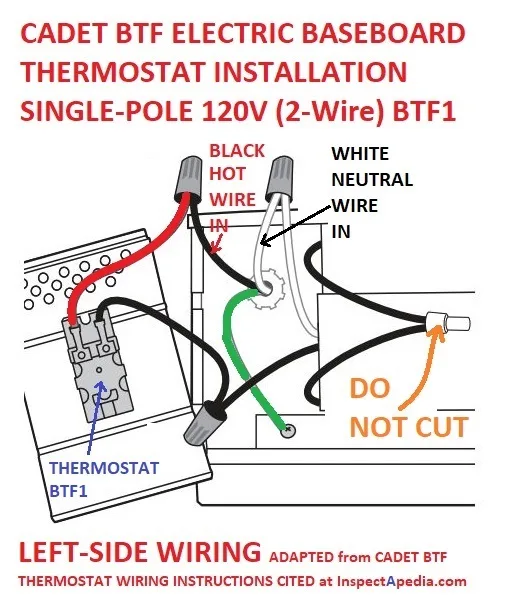
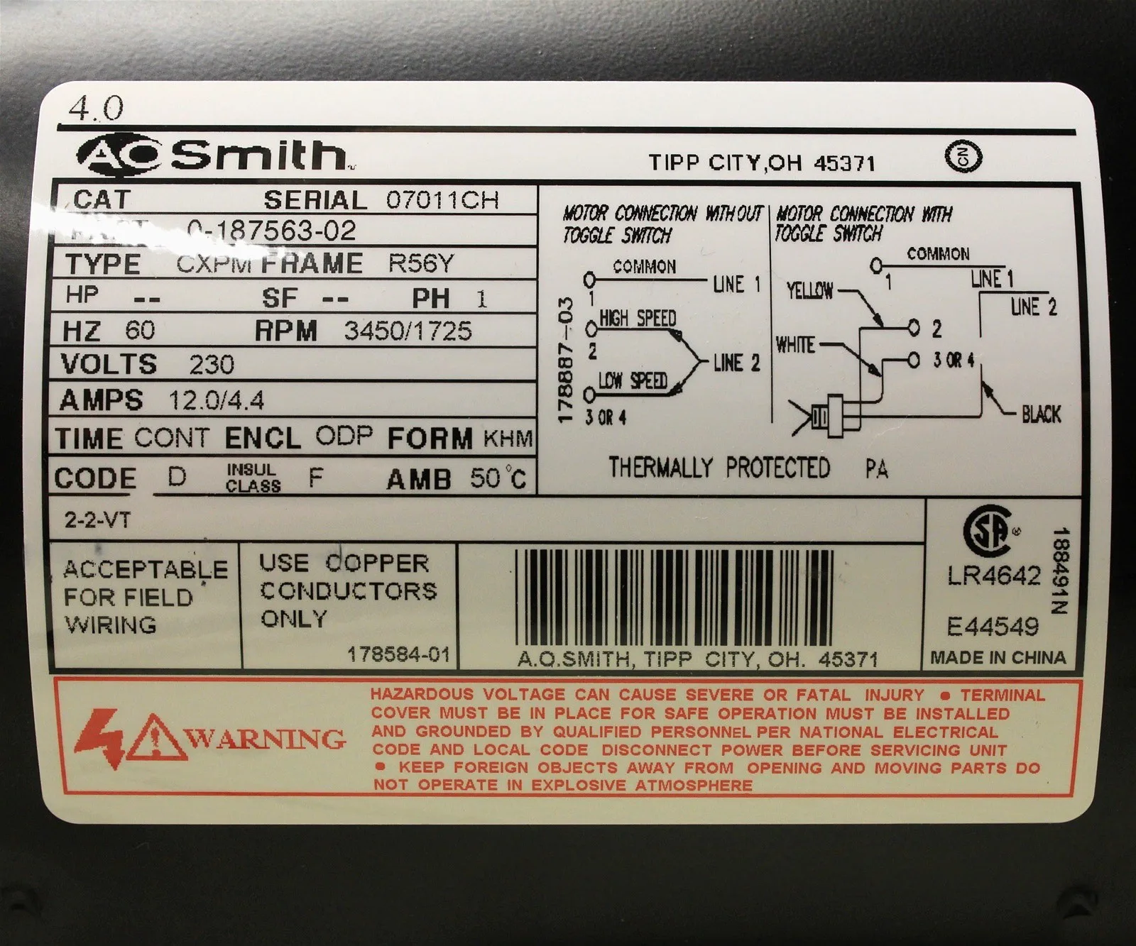
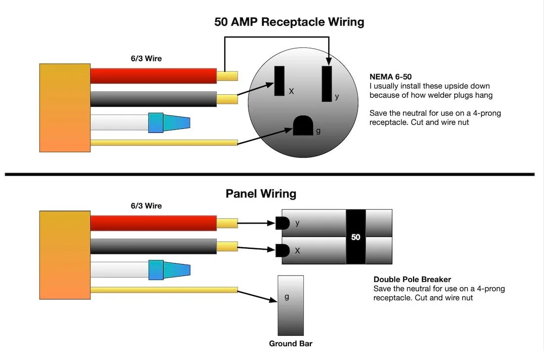
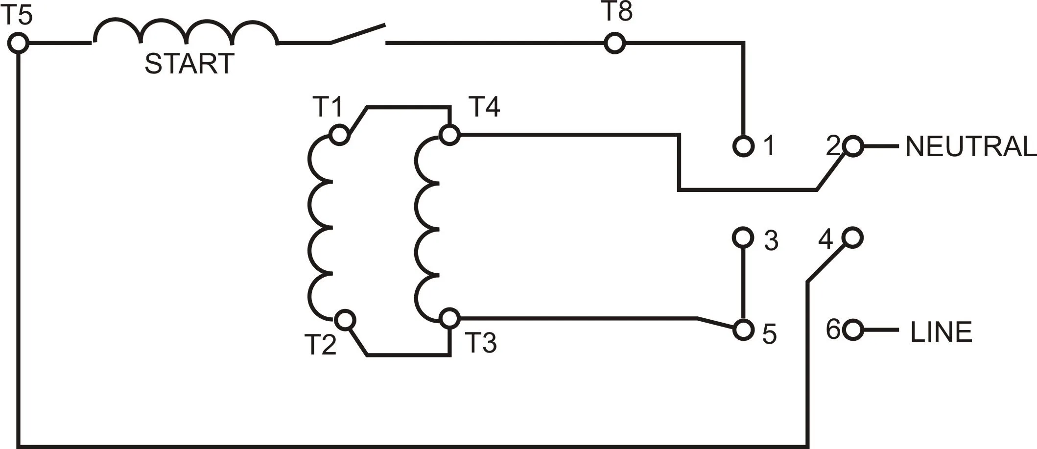
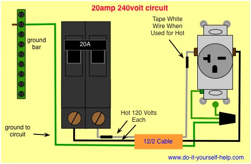
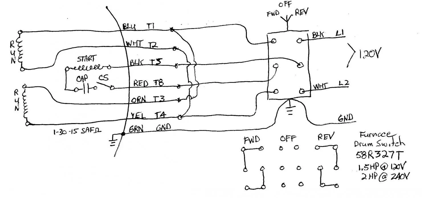
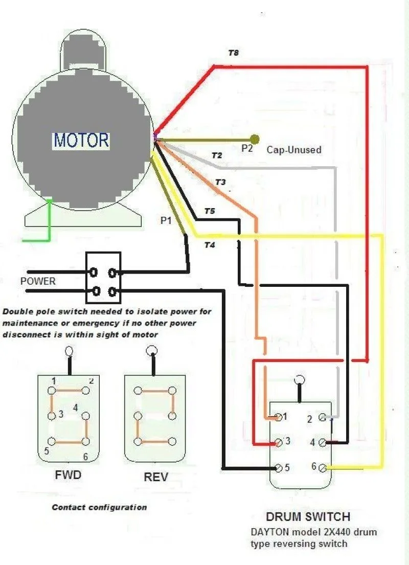
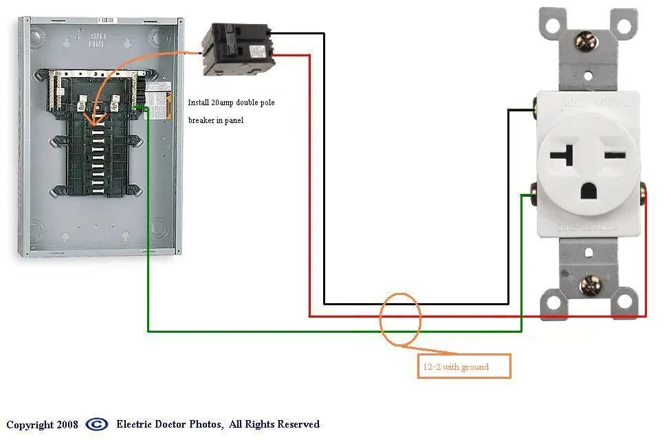
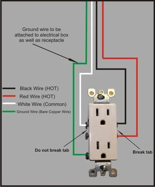
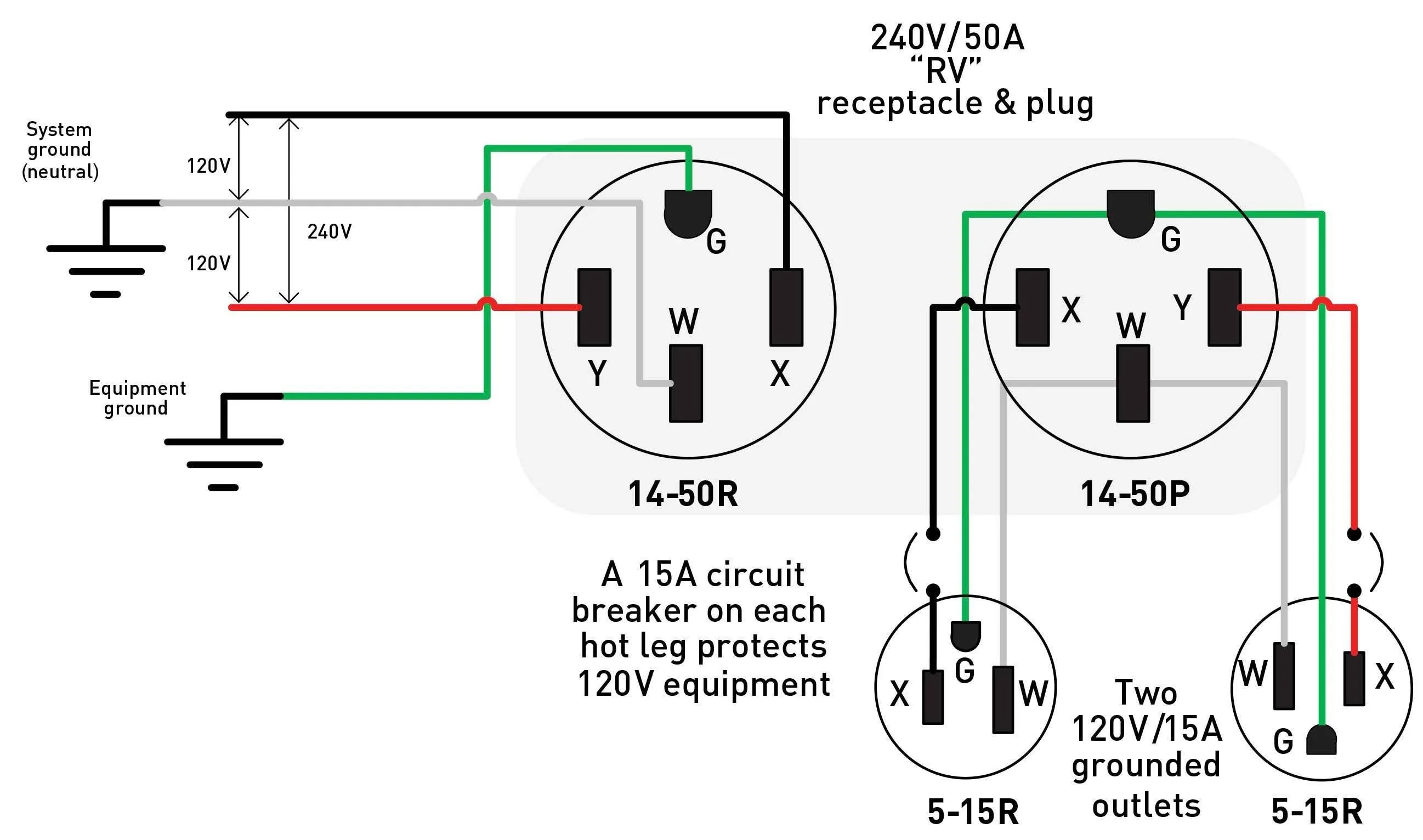
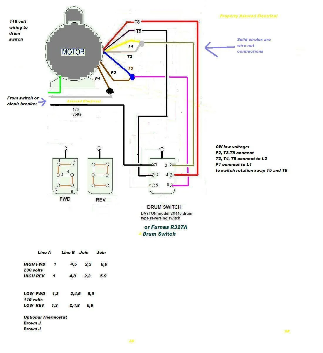
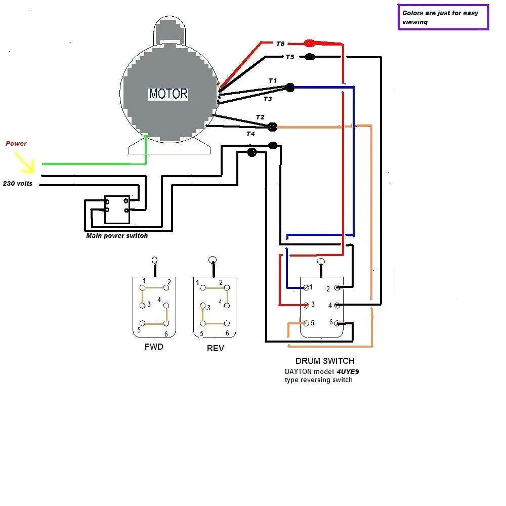
A wiring diagram is a schematic representation of an electrical circuit. It shows the components of the circuit as simplified shapes, and the power and signal connections between the devices. A 110 volt wiring diagram, as the name suggests, shows the connections and components of a circuit that runs on 110 volts, which is the standard voltage used in most homes and buildings in the United States. This diagram is used by electricians and engineers to create, repair or modify electrical circuits.

110 volt wiring diagrams typically consist of basic circuit symbols such as wires, switches, and outlets. They also include more complex symbols such as relays, transformers, and capacitors. These symbols are used to represent the different components of a circuit and their connections. The diagram will also show the flow of electricity through the circuit, which helps in troubleshooting any problems that may occur.

Table 1. Basic Circuit Symbols Used in 110 Volt Wiring Diagrams

Symbol Description
Wires Represents the electrical connection between components
Switches Controls the flow of electricity by opening or closing the circuit
Outlets A device used to connect electrical equipment to the circuit
Relays A switch that is controlled by electricity and is used to control other devices
Transformers A device that changes the voltage of electricity from one level to another
Capacitors A device that stores electrical energy

Applications of 110 Volt Wiring Diagrams

110 volt wiring diagrams have a wide range of applications in different industries. Some of the most common uses include:

Residential Wiring

The 110 volt wiring system is used in homes to power electrical appliances such as lights, fans, and televisions. Proper wiring is essential for the safety and functionality of the electrical system in homes.

Commercial Wiring

Offices, malls, and other commercial buildings use 110 volt wiring systems to power their electrical equipment. Commercial wiring often requires more complex wiring diagrams that incorporate multiple circuits and devices.

Industrial Wiring

Factories, manufacturing plants, and other industrial facilities require robust electrical systems that can handle high voltage and power requirements. 110 volt wiring diagrams are used in these settings to plan and install electrical systems that can handle the specific needs of the industry.

Creating a 110 Volt Wiring Diagram

Creating a 110 volt wiring diagram requires a basic understanding of electrical circuits and their components. Here are the steps to creating a simplified 110 volt wiring diagram:

Step 1: Identify the Components

Identify the components you want to include in the circuit, such as switches, outlets, and lights. Draw each component as a symbol on the diagram.

Step 2: Plan the Circuit

Plan the circuit by defining the path that electricity will flow through the system. Use arrows to indicate the direction of the current flow.

Step 3: Calculate the Voltage and Amperage

Calculate the voltage and amperage requirements of the circuit by adding up the power requirements of each device. This will help you choose the right wire size and other components for your circuit.

Step 4: Check for Errors

Check your diagram for any errors or inconsistencies. Make sure each component is properly labeled and connected, and that the circuit meets the requirements of the devices it will be powering.

Step 5: Finalize the Diagram

Finalize your diagram by adding a title, date, and any notes or comments that may be helpful for future reference. Save your diagram as a digital file or print it out for use in the field.

Frequently Asked Questions

What is the difference between a 110 volt and 220 volt wiring diagram?

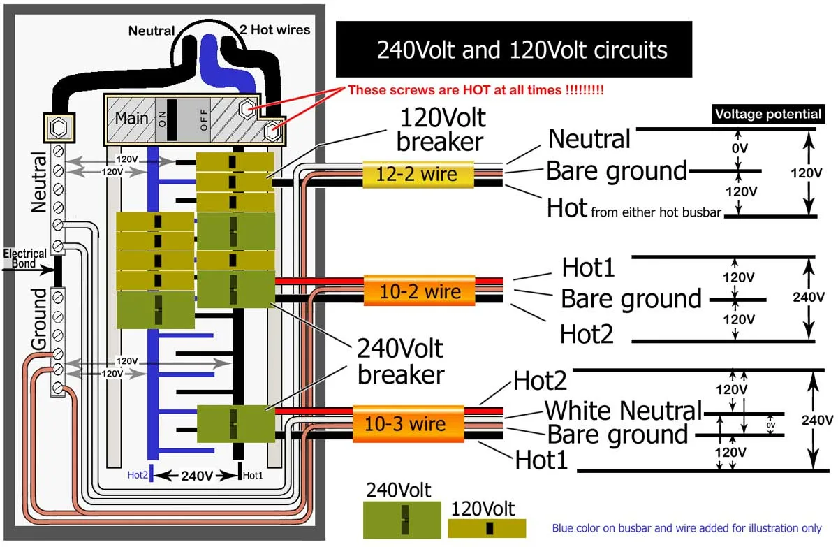
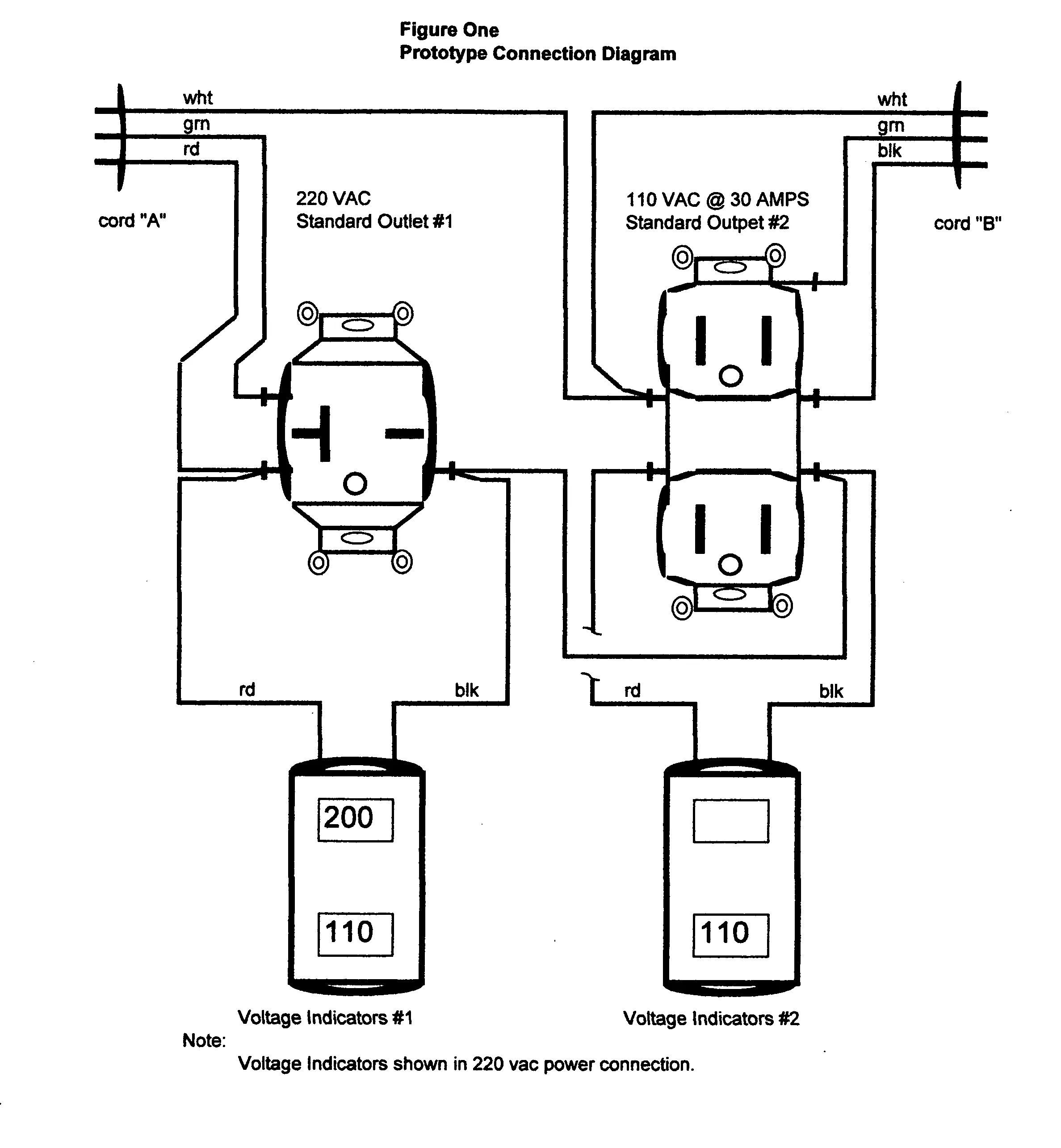
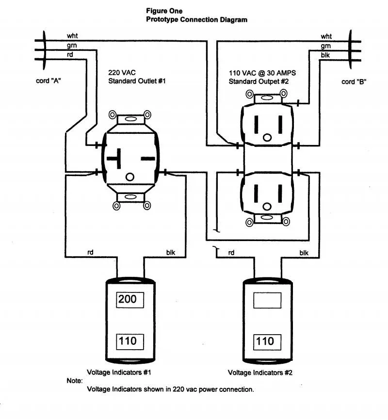
A 110 volt wiring diagram shows the components and connections for a circuit that runs on 110 volts, while a 220 volt wiring diagram shows the components and connections for a circuit that runs on 220 volts. The higher voltage allows for more power to be delivered to electrical devices, but it also requires larger and more robust wiring and components.

Can I create a 110 volt wiring diagram on my own?

Yes, anyone with a basic understanding of electrical circuits and their components can create a 110 volt wiring diagram. However, it is recommended to work with a licensed electrician or engineer to ensure that the diagram meets safety standards and local building codes.

What are some common mistakes to avoid when creating a 110 volt wiring diagram?

Common mistakes include incorrect labeling of components, incorrect wiring diagrams, and using incorrect wire sizes or types. It is important to double-check your work and consult with a professional if you are unsure about any aspect of the diagram.

How can I troubleshoot a problem with my 110 volt wiring system?

If you are experiencing issues with your electrical system, start by checking the connections and components in the diagram. Look for loose or damaged wires, switches, or outlets. If you are still unable to find the issue, consult with a licensed electrician or engineer for further assistance.

Conclusion

Understanding 110 volt wiring diagrams is an essential part of working with electrical circuits. Whether you are working on a residential, commercial, or industrial project, creating a clear and concise diagram can help you plan and execute a safe and effective electrical system. By following the steps outlined in this article, you can create a simplified 110 volt wiring diagram that meets your specific needs and requirements.