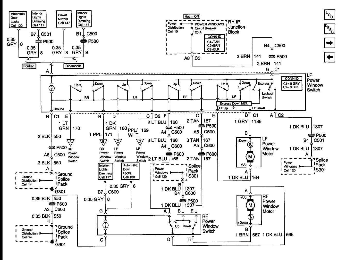
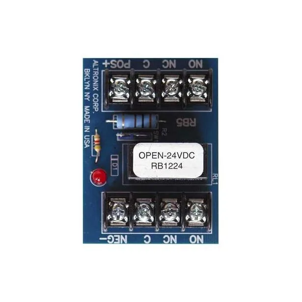
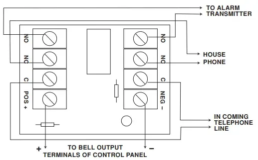
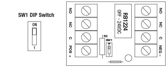
Altronix Relay Wiring Diagram

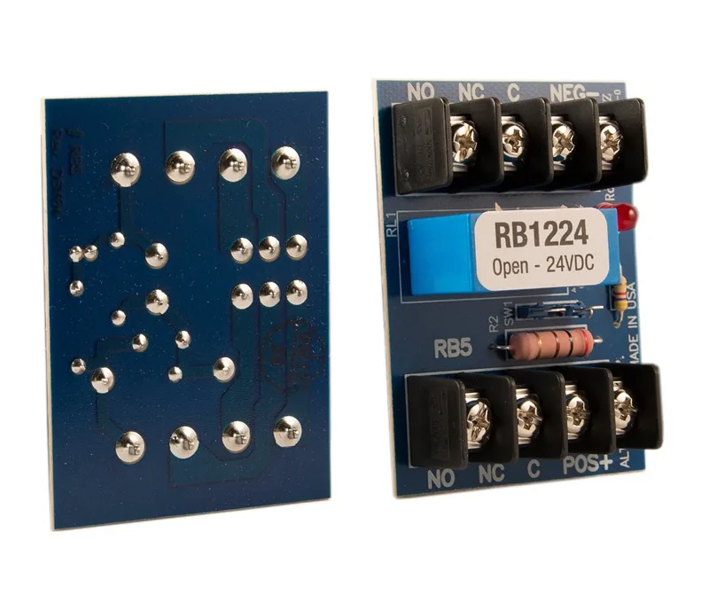
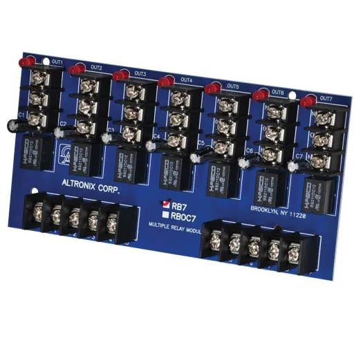
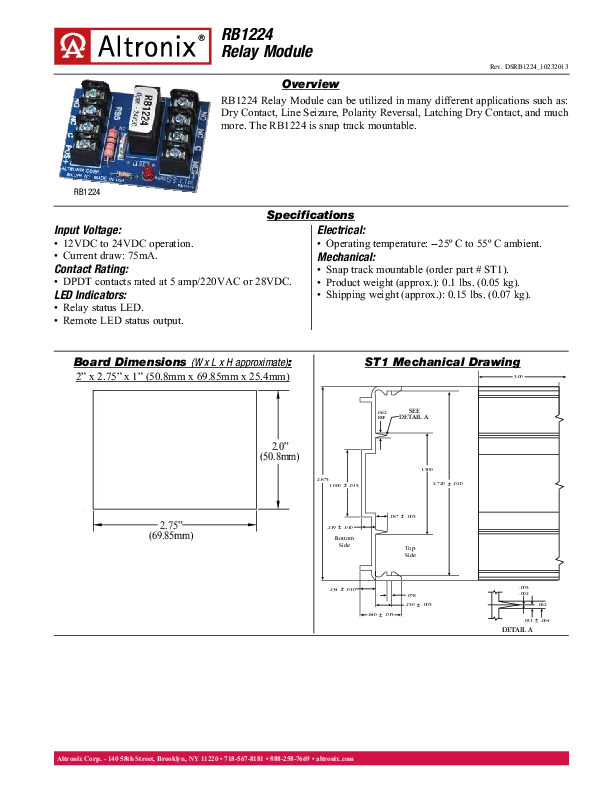
Relays are the electro-mechanical devices used to control the circuits electrically. They switch on and off the electronic devices of the electrical circuits using an electromagnetic coil for controlling the current flow. In electronic devices, a relay is essential as it acts as an interface between the low voltage circuits and high power circuits. Altronix is a well-known brand for manufacturing idle electrical devices for years. This article will focus on the Altronix relay wiring diagram, its features, benefits and frequently asked questions.

Introduction to Altronix Relay Wiring Diagram

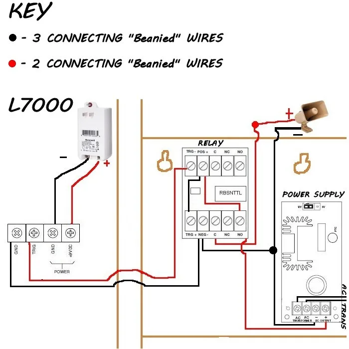
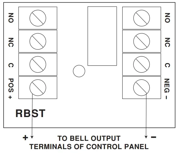
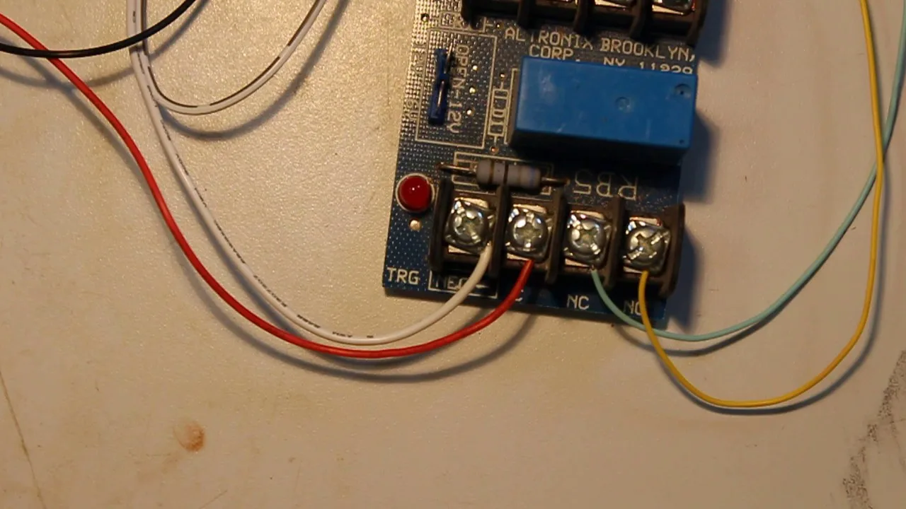
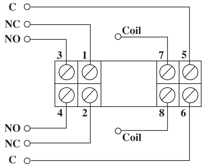
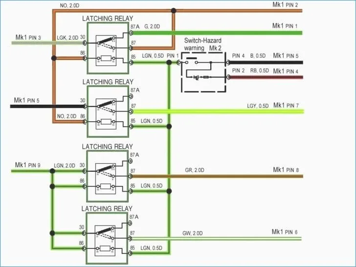
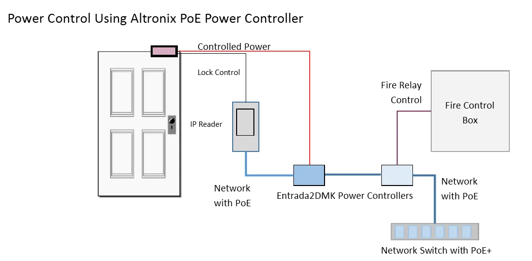
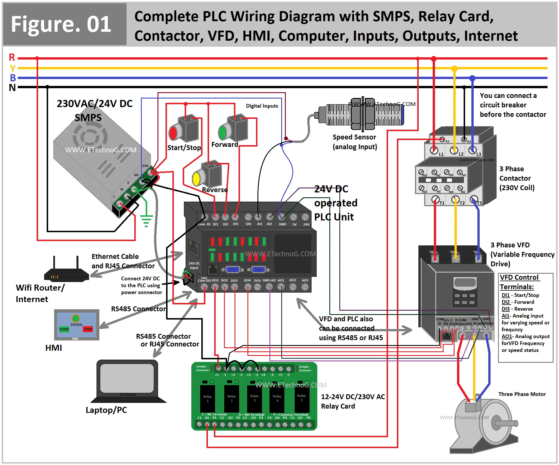
The Altronix relay wiring diagram is a blueprint that guides the installation and connection of the Altronix relay with the supporting devices. The Altronix relay and its wiring diagram are suitable for various types of electrical circuits like access control systems, CCTV cameras, and fire alarms, etc. The wiring diagram consists of different symbols and connections that show the wiring of the relay with other supporting devices.

Altronix relay wiring diagrams come with several user-friendly features, including:

  • Clear and easy-to-understand wiring instructions
  • Compatibility with various devices
  • Available in different versions depending on the application
  • Robust and long-lasting design

Benefits of Using Altronix Relay Wiring Diagram
The advantages of using an Altronix relay wiring diagram include:

  • Easy installation: The Altronix relay wiring diagram eases the installation process by providing a clear connection guide.
  • Cost-effective: The Altronix relay wiring diagram is cost-effective as it reduces the risk of mistakes that might lead to electrical equipment damage.
  • Improved efficiency: The correct installation of the relay with the supporting devices under the guidance of the Altronix relay wiring diagram enhances the overall efficiency of the circuit and ensures the correct functioning of the devices.
  • Fewer callbacks: The Altronix relay wiring diagram ensures proper installation and connection, which leads to fewer callbacks for maintenance.

How to Read an Altronix Relay Wiring Diagram
The symbols used in the Altronix relay wiring diagram represent different electrical components or devices. In the wiring diagram, the relay is represented by a rectangular box with two triangles on the top of the box (representing the electromagnetic coil). Each line represents a wire connecting the components. The + (plus) sign represents the positive wire, and the – (minus) sign represents the negative wire.

Other symbols include:

  • Resistor (zigzag line): Represents a device that resists the flow of current to control the voltage.
  • Capacitor (parallel lines): Represents a device that stores electrical energy.
  • Diode (arrow): Represents a device that controls the direction of the current flow in a circuit.
  • Transformer (two coils): Represents a device that converts one level of voltage to another.

Altronix Relay Wiring Diagram FAQs

1. How can I check the compatibility of the Altronix relay wiring diagram with my device?

You can check the wiring diagram’s compatibility with your device by comparing the circuit layout and the supporting devices with the diagram. If the layout is similar or identical, then the wiring diagram is compatible with your device.

2. What should I do if I am facing difficulty in reading the Altronix relay wiring diagram?

If you are facing problems reading the diagram, it is better to consult a professional electrician or a technical support team. They can guide you through the process and help you understand the diagram better.

3. Can I use an Altronix relay wiring diagram for different applications?

Yes, you can use the Altronix relay wiring diagram for different applications as it comes in different versions depending on the application.

Conclusion

The Altronix relay wiring diagram is an essential tool for the installation and connection of the Altronix relay with the supporting devices. The wiring diagram is user-friendly and easy to understand, making it suitable for both professionals and non-professionals. It guides the correct installation and connection of the relay with the supporting devices, leading to the overall efficiency of the circuit and ensuring the devices’ correct functioning.