Actuator Relay Wiring Diagram: A Comprehensive Guide

Actuator relays are essential components in many electrical systems. They are used to control the flow of electrical current to different parts of a system. Actuator relays can be found in a wide range of applications, such as in automotive systems, aerospace systems, and industrial systems.

What is an Actuator Relay?

An actuator relay is an electrical switch that is used to control the flow of electrical current to different parts of a system. It is a type of relay that is specifically designed to control an actuator, such as a motor or solenoid. Actuator relays are used in a wide range of applications, such as in automotive systems, aerospace systems, and industrial systems.

Actuator relays can be either normally open (NO) or normally closed (NC). A normally open actuator relay is one that is open when it is not energized, and closes when it is energized. Conversely, a normally closed actuator relay is one that is closed when it is not energized, and opens when it is energized.

Types of Actuator Relays

There are several different types of actuator relays, including:

Type Description
Electromechanical relays These are the most common type of actuator relay. They use electromagnetic coils to open and close the contacts.
Solid state relays These relays use semiconductor components, such as transistors, to control the flow of electrical current.
Reed relays These relays use a magnetic field to control the contacts.
Hybrid relays These relays combine the features of electromechanical and solid state relays.

Actuator Relay Wiring Diagram
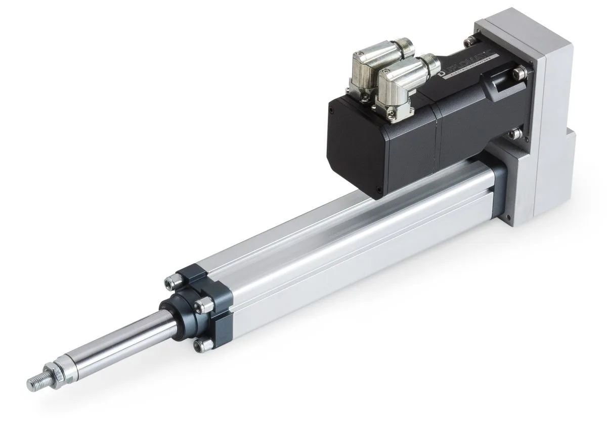
An actuator relay wiring diagram is a schematic representation of the electrical connections that are required to control an actuator using a relay. The wiring diagram shows the various components of the system, including the actuator, the relay, the power supply, and the control circuit.

The wiring diagram will vary depending on the specific application and the type of actuator relay that is being used. However, there are some general principles that apply to most actuator relay wiring diagrams.

Actuator Relay Wiring Diagram Components
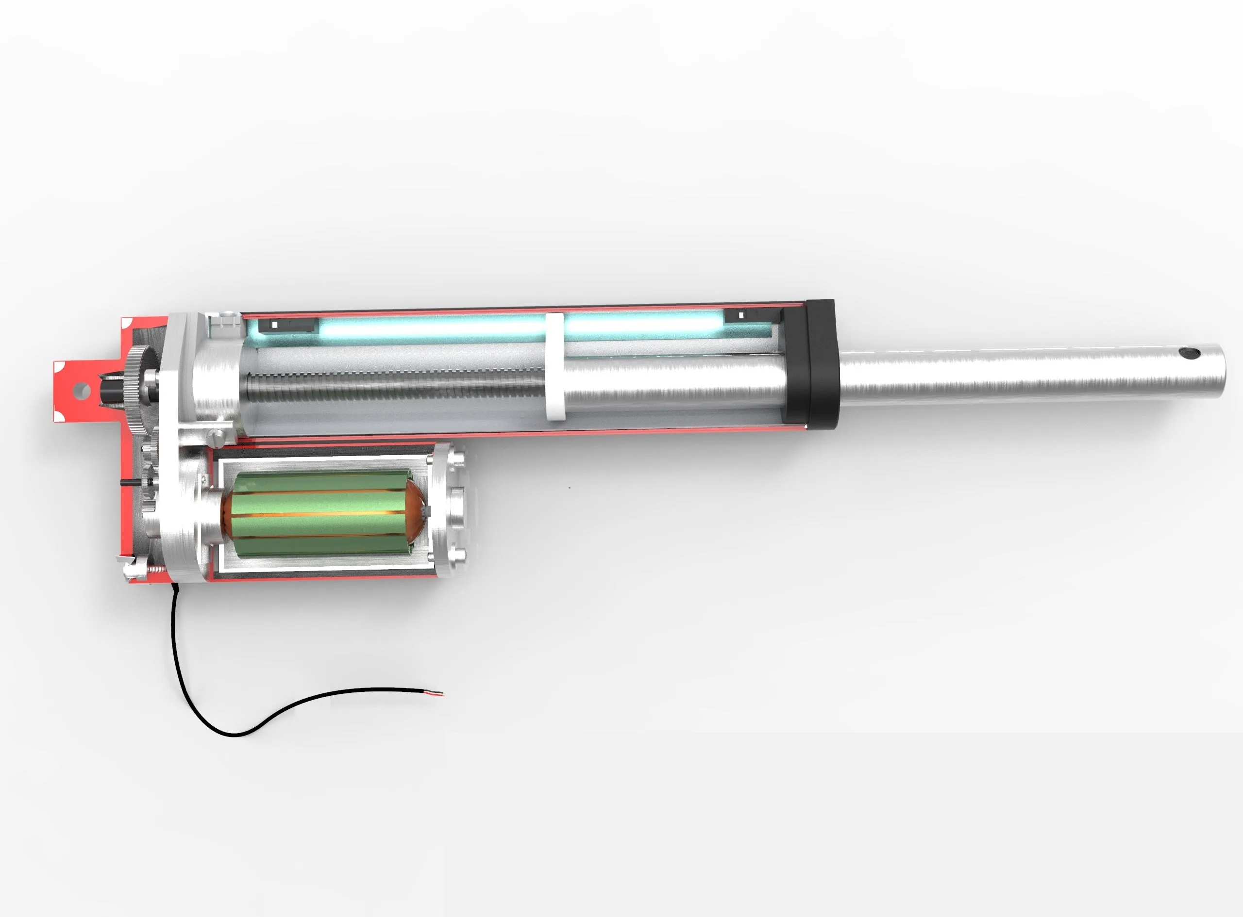
The following components are typically included in an actuator relay wiring diagram:

  • Actuator
  • Relay
  • Power supply
  • Control circuit

The actuator is the component that is being controlled by the relay. It could be a motor, a solenoid, or any other type of actuator. The relay is the switch that is used to control the flow of electrical current to the actuator. The power supply is the source of electrical power that is used to energize the relay and the actuator. The control circuit is the circuit that provides the signal to the relay to open and close the contacts.

Wiring Diagram Example

Here is an example of an actuator relay wiring diagram:

Actuator Relay Wiring DiagramSource: bing.com

In this wiring diagram, the actuator is a motor, the relay is an electromechanical relay, the power supply is a battery, and the control circuit is a switch. When the switch is closed, it completes the control circuit, which energizes the relay. The relay then closes the contacts, which allows electrical current to flow from the battery to the motor. The motor then activates and performs its intended function.

FAQs

What is the purpose of an actuator relay?

An actuator relay is used to control the flow of electrical current to an actuator, such as a motor or solenoid. It is a type of switch that is specifically designed to control an actuator.

What are the different types of actuator relays?

There are several different types of actuator relays, including electromechanical relays, solid state relays, reed relays, and hybrid relays.

What is an actuator relay wiring diagram?

An actuator relay wiring diagram is a schematic representation of the electrical connections that are required to control an actuator using a relay. It shows the various components of the system and the electrical connections between them.

What components are typically included in an actuator relay wiring diagram?

The components that are typically included in an actuator relay wiring diagram are the actuator, the relay, the power supply, and the control circuit.

How do I read an actuator relay wiring diagram?

To read an actuator relay wiring diagram, you should first familiarize yourself with the symbols used for the various components. Once you understand the symbols, you can then follow the wiring diagram to determine the electrical connections between the components.