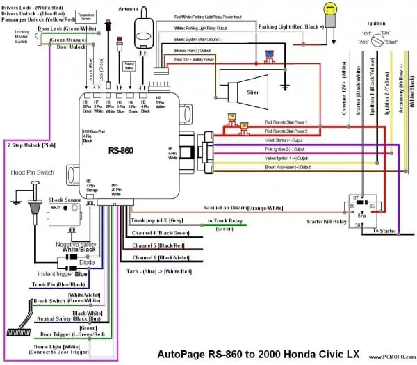
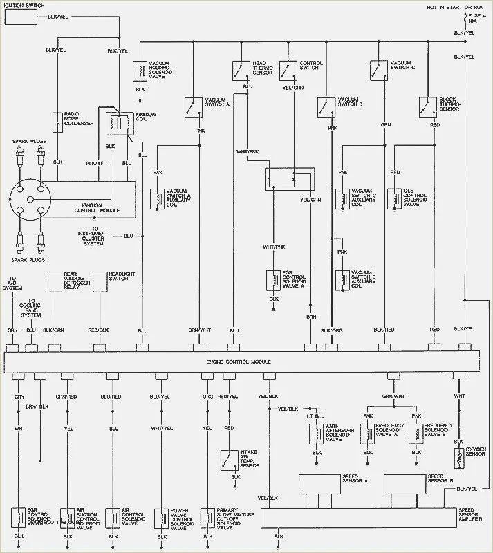
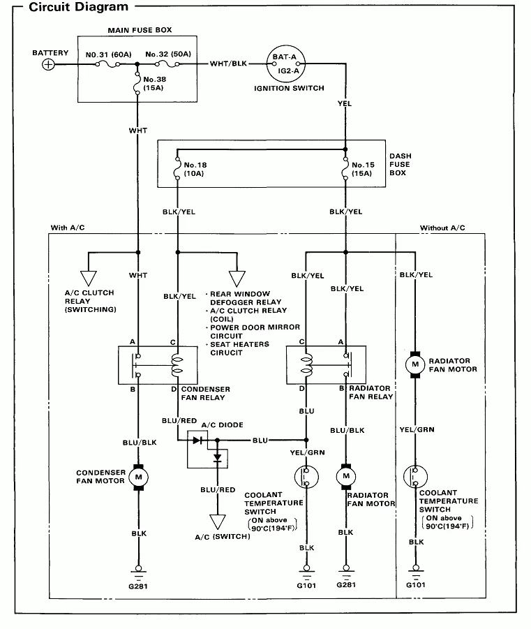
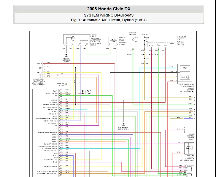
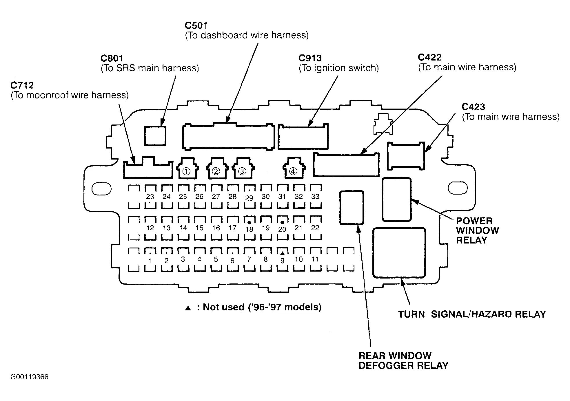
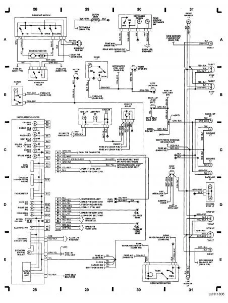
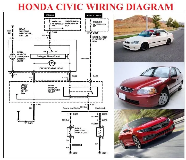
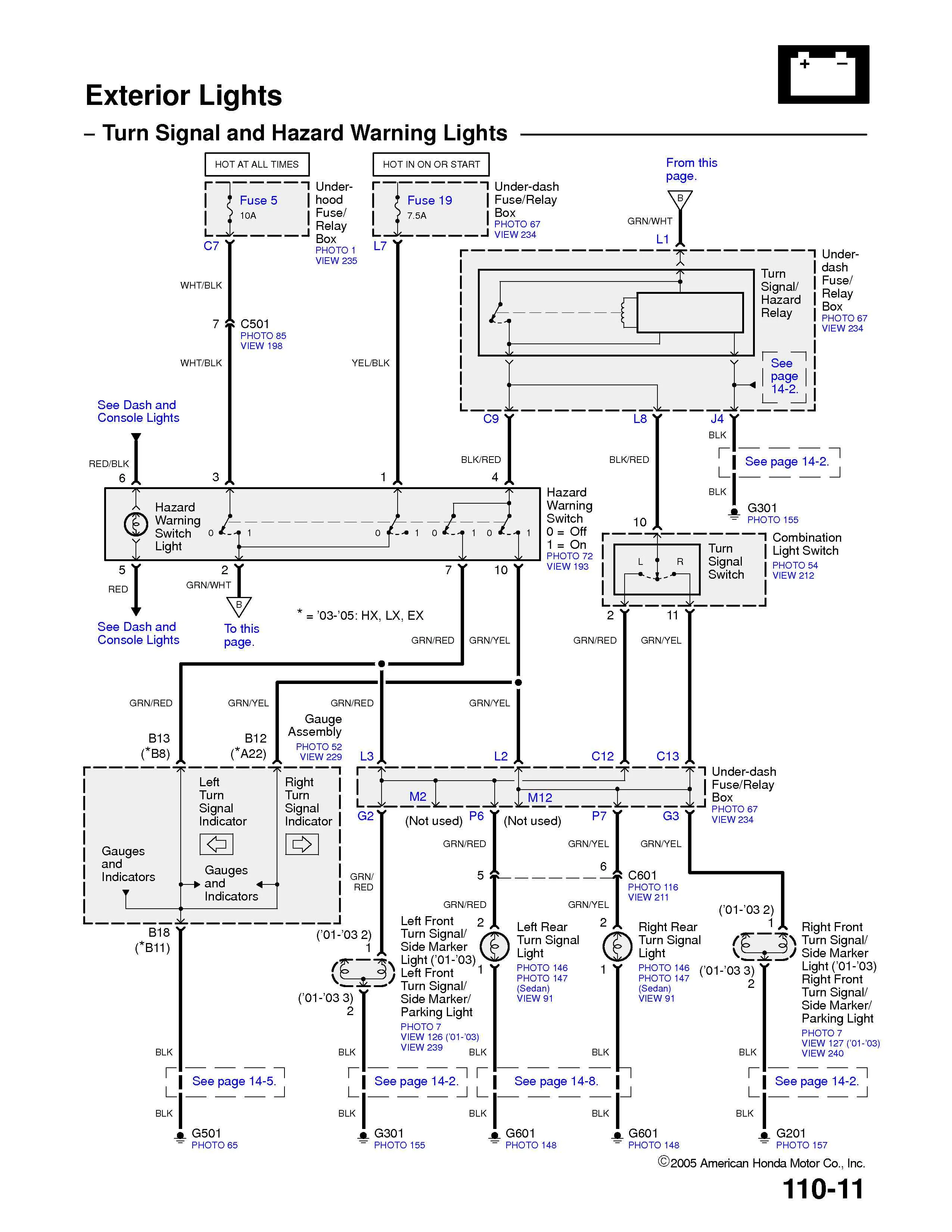
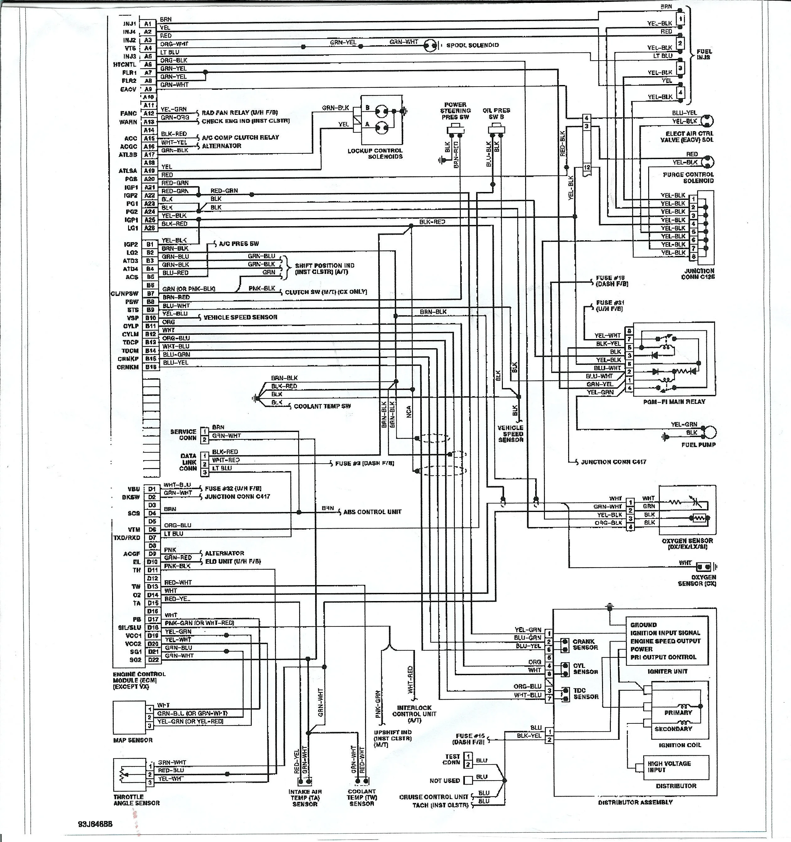
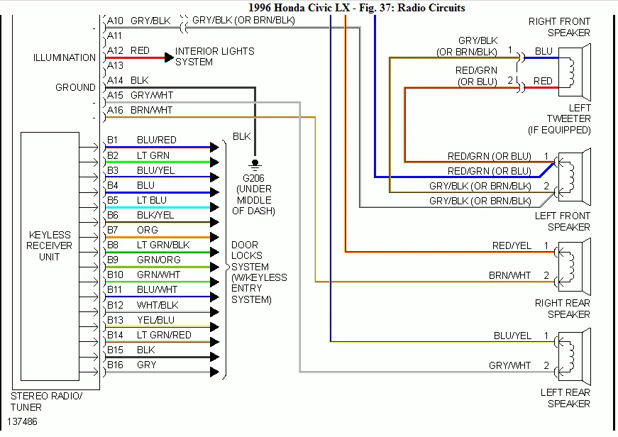
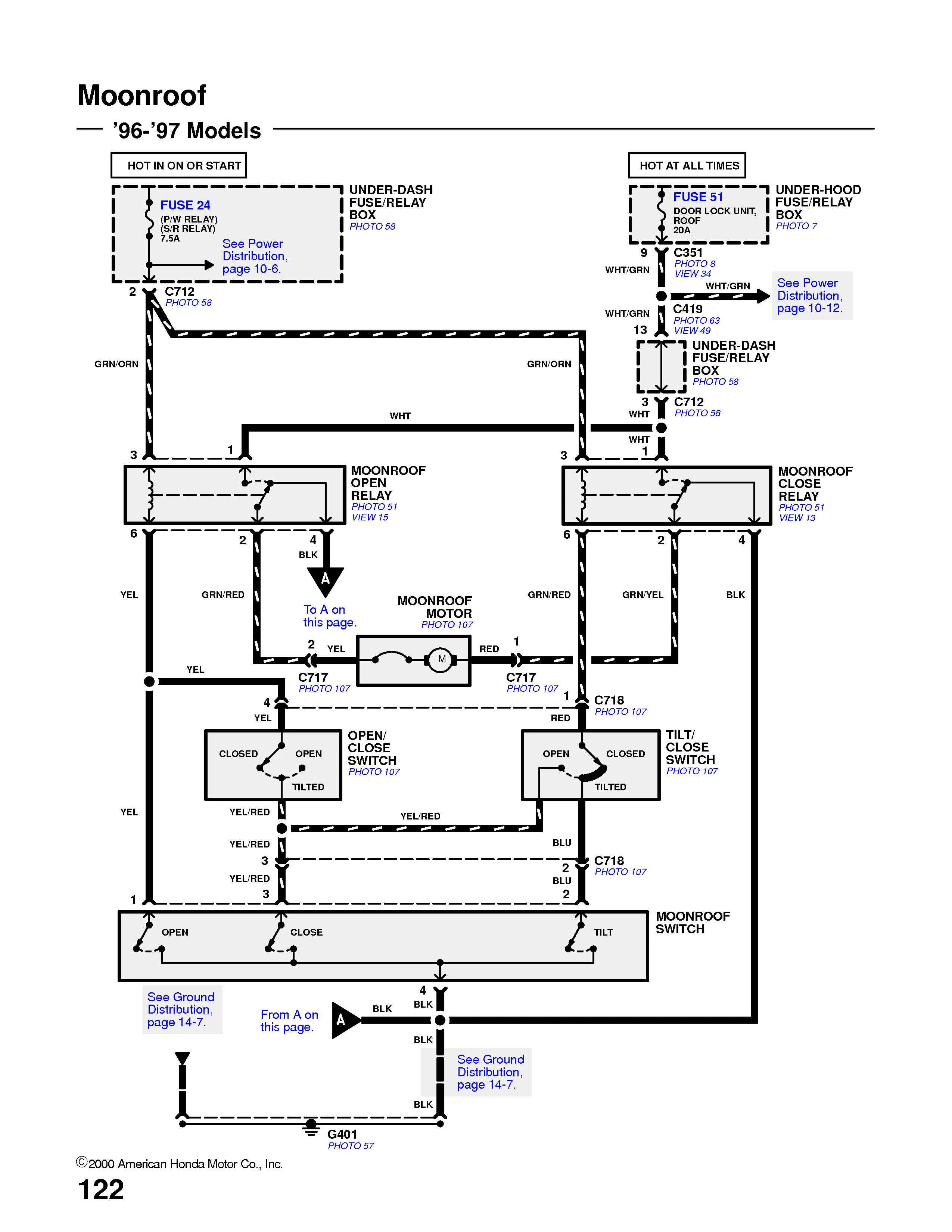
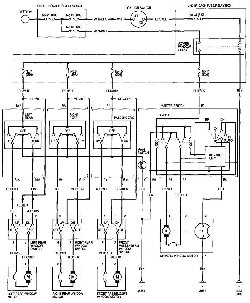
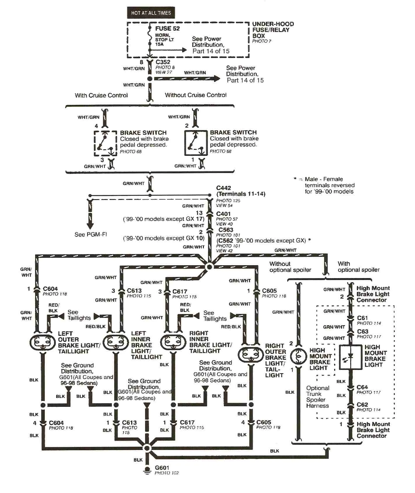
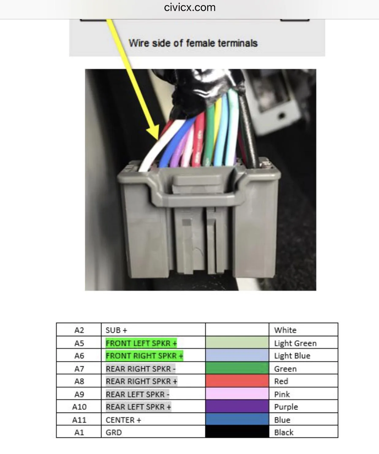
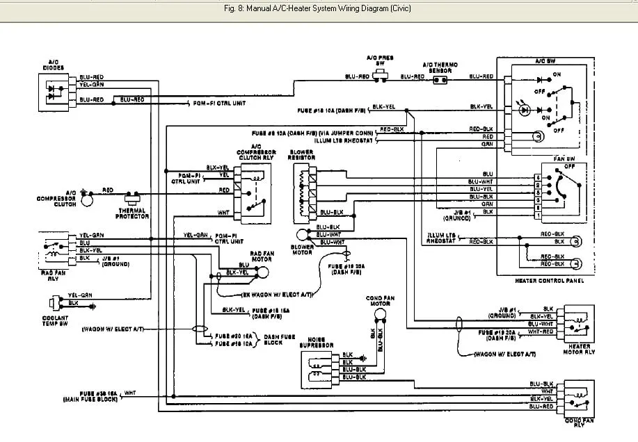
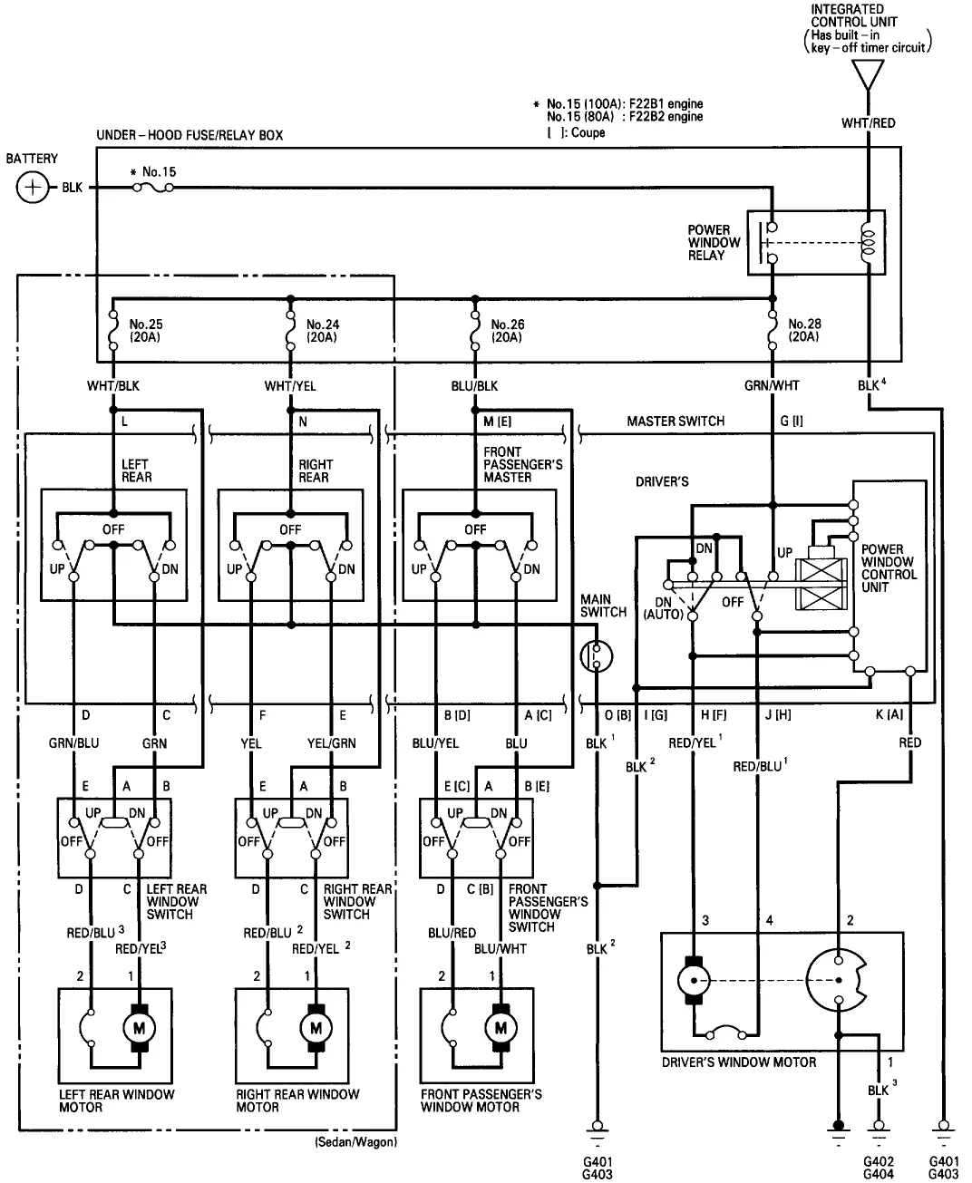
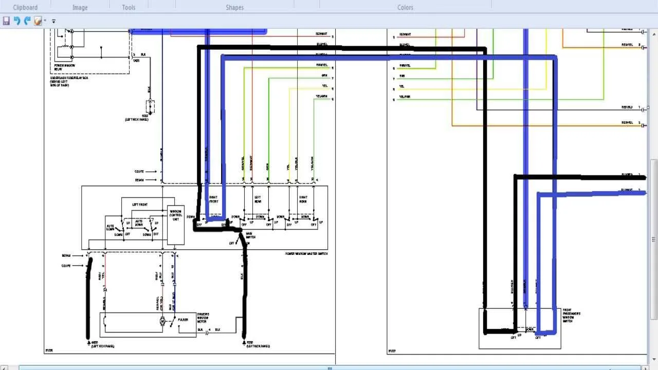
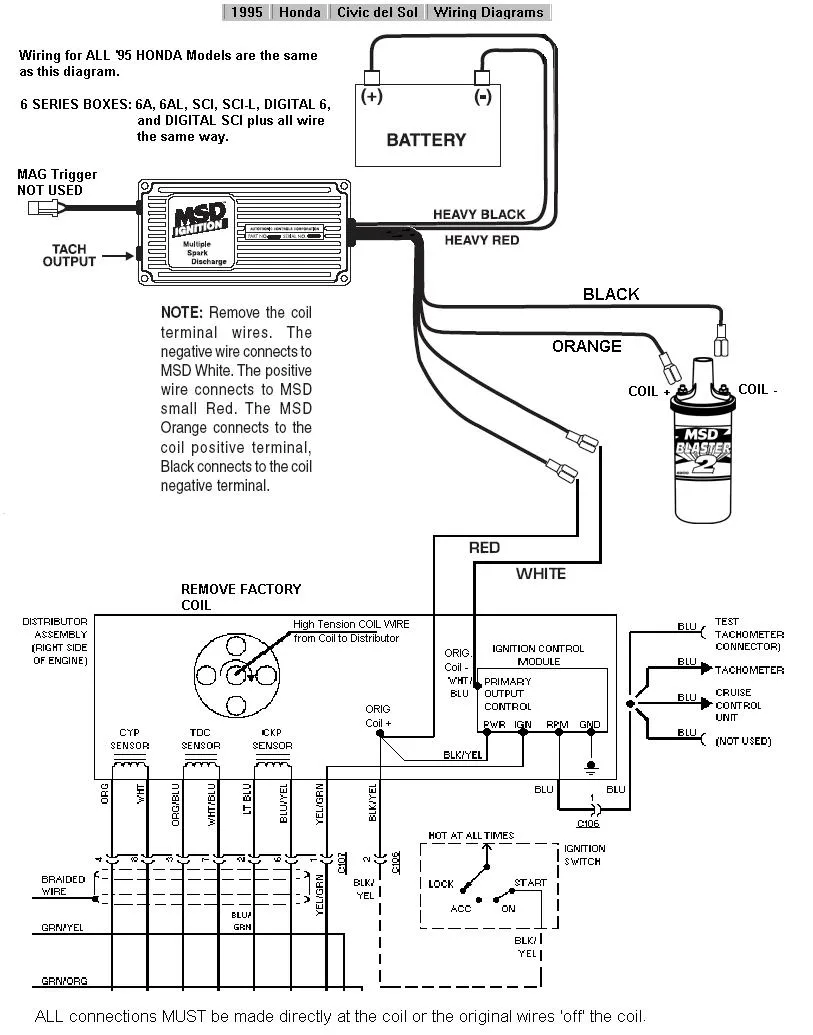
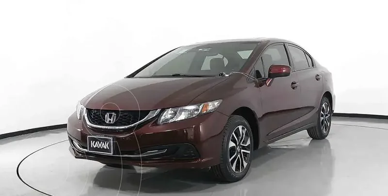
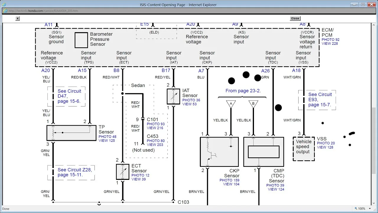
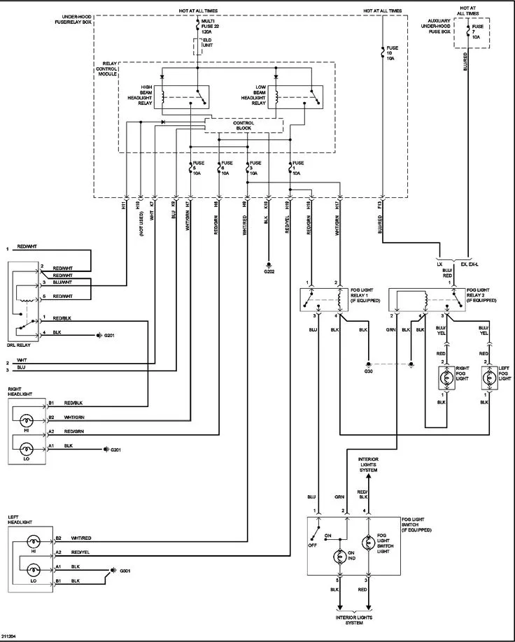
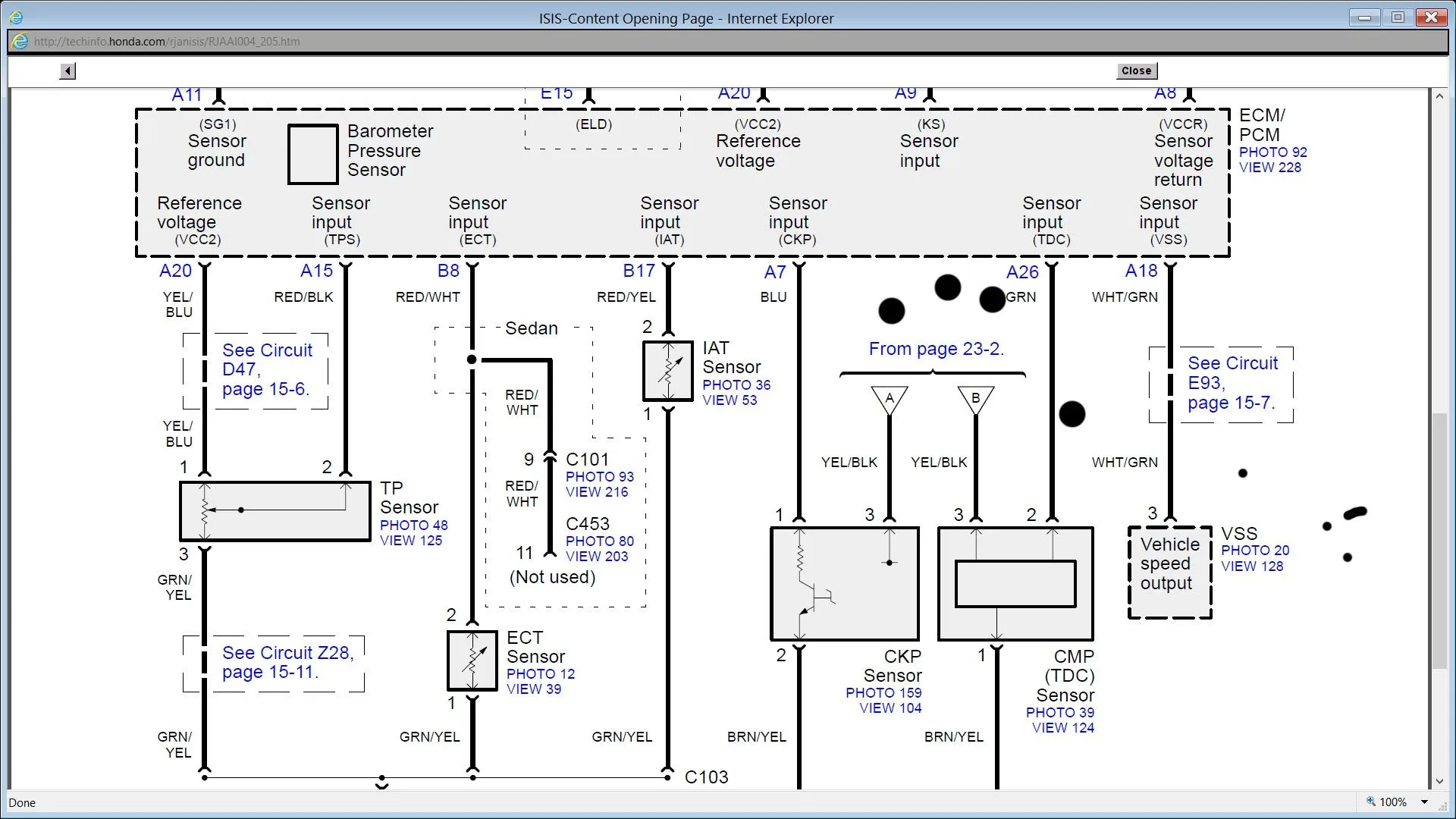
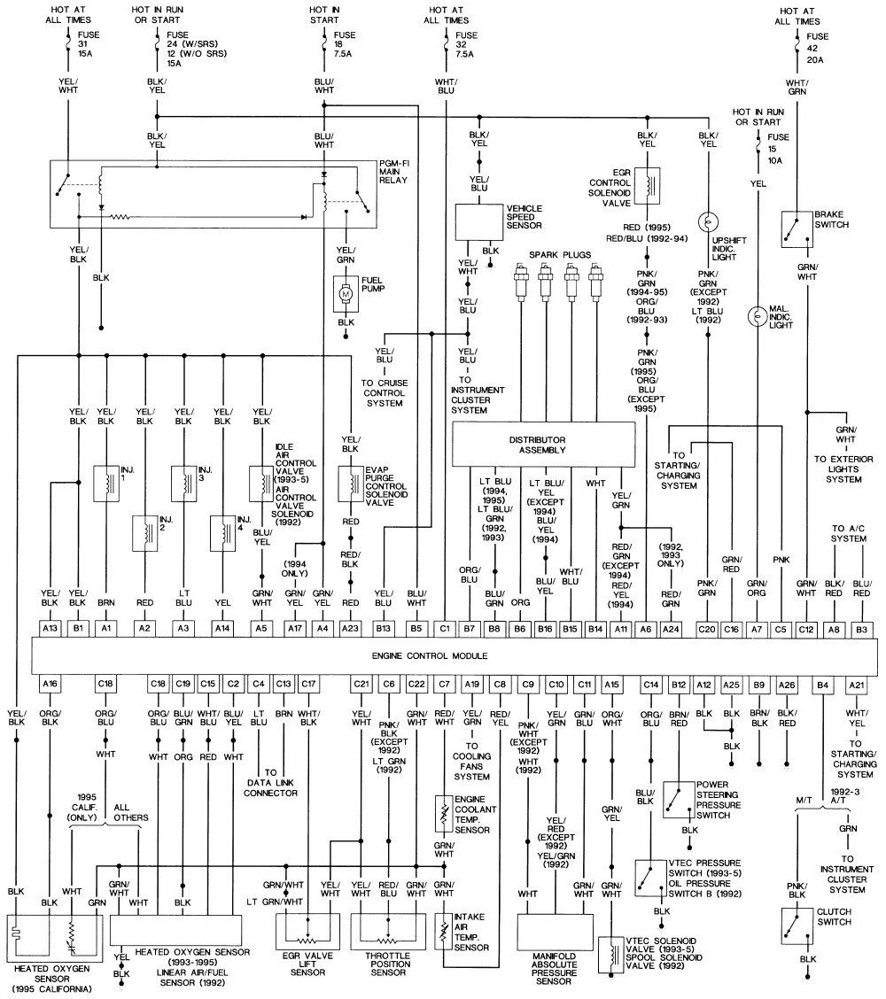
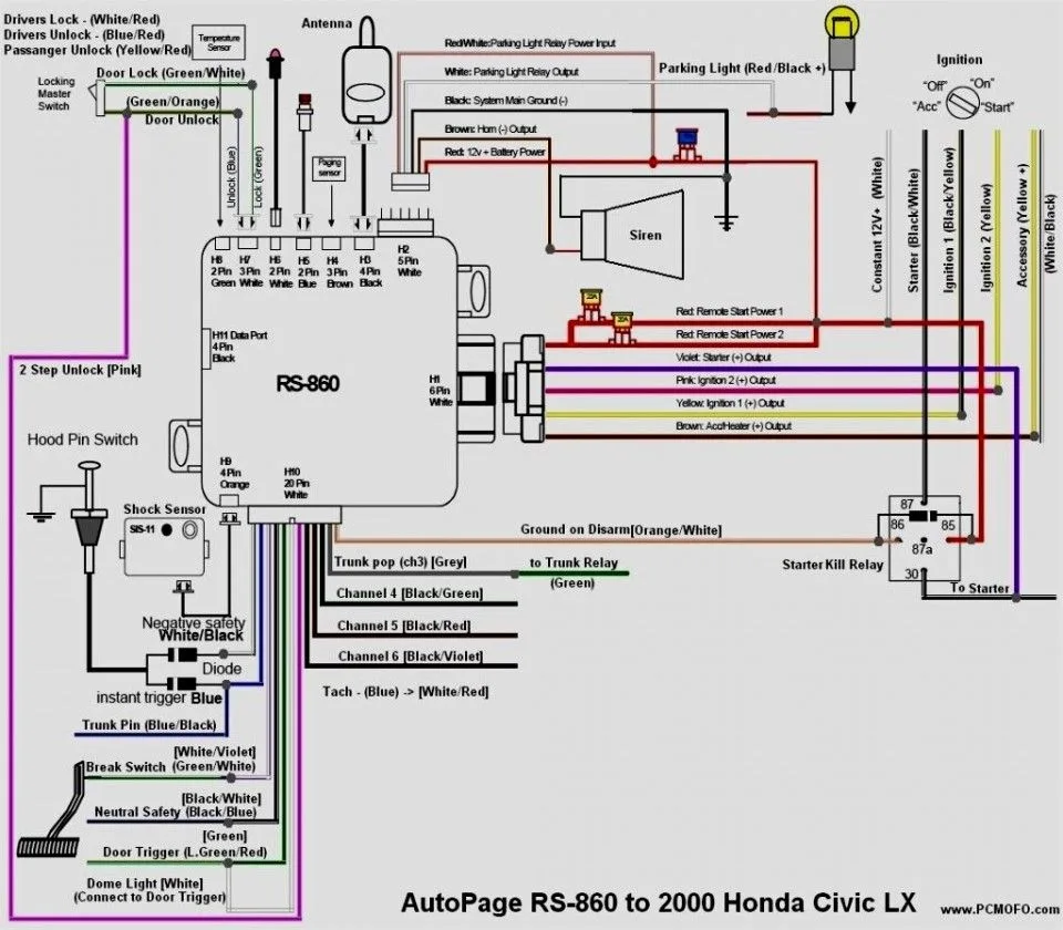
The 2015 Honda Civic wiring diagram provides a clear illustration of the electrical connections and components within the vehicle. The wiring diagram is an essential tool for troubleshooting any electrical issues that may arise with your Civic. In this article, we will review the 2015 Honda Civic wiring diagram and provide a detailed breakdown of the various components and connections.
What is a Wiring Diagram?
A wiring diagram is a visual representation of the electrical connections and components within a vehicle. It provides a clear illustration of how the various components are connected, allowing for easy troubleshooting and repair of any electrical issues that may arise. The wiring diagram is an essential tool for any mechanic or DIY enthusiast and is often included in the vehicle’s owner’s manual.
How to Read a Wiring Diagram
Before we dive into the 2015 Honda Civic wiring diagram, it’s important to understand how to read a wiring diagram. Wiring diagrams consist of several symbols and lines, each representing a specific component or connection. The symbols used in wiring diagrams can vary depending on the manufacturer and model of the vehicle, but there are some common symbols that are used across the automotive industry.
Lines: The lines on a wiring diagram represent the wires that connect the various components. They can be solid, dashed, or dotted lines, and each line represents a different type of wire, such as power or ground.
Symbols: Symbols are used to represent specific components within the vehicle, such as a battery, starter, or alternator. Each symbol has its own unique shape and is often accompanied by a label that indicates what component it represents.
Colors: The colors of the lines on a wiring diagram can also provide important information. For example, a red line may indicate a power source, while a black line may indicate a ground connection.
2015 Honda Civic Wiring Diagram Components
The 2015 Honda Civic wiring diagram includes a variety of components, each of which plays a unique role in the vehicle’s electrical system. Some of the key components and connections included in the wiring diagram are:
Component | Description |
---|---|
Battery | The battery provides power to the vehicle’s electrical system. |
Starter | The starter is responsible for turning the engine over when the ignition is turned on. |
Alternator | The alternator is responsible for charging the battery and providing power to the vehicle’s electrical system while the engine is running. |
Fuses | Fuses are designed to protect the vehicle’s electrical system by preventing excessive current from flowing through the system. |
Relays | Relays are used to control the flow of electricity to various components within the vehicle. |
Switches | Switches are used to control various functions within the vehicle, such as the headlights or windshield wipers. |
Battery
The battery is a critical component within the vehicle’s electrical system. It provides power to the starter and other components when the engine is not running, and is also responsible for powering the vehicle’s electrical system when the engine is running. The battery is typically located under the hood of the vehicle and is connected to the vehicle’s electrical system via a series of cables and connectors.
Starter
The starter is responsible for turning the engine over when the ignition is turned on. It is typically located on the bottom of the engine block and is connected to the battery and ignition switch via a series of wires and connectors. When the ignition is turned on, the starter engages with the flywheel on the engine and turns the engine over, allowing it to start.
Alternator
The alternator is responsible for charging the battery and providing power to the vehicle’s electrical system while the engine is running. It is typically located near the top of the engine block and is connected to the battery and other components via a series of wires and connectors. When the engine is running, the alternator generates electricity and sends it to the battery, which then powers the vehicle’s electrical system.
Fuses
Fuses are designed to protect the vehicle’s electrical system by preventing excessive current from flowing through the system. When too much current flows through a circuit, the fuse will “blow,” cutting off the flow of electricity and preventing damage to the system. Fuses are typically located in a fuse box under the dash or hood of the vehicle and are labeled according to their amperage rating.
Relays
Relays are used to control the flow of electricity to various components within the vehicle. They are essentially switches that are controlled by an electrical signal. When the relay receives a signal, it switches on or off, allowing or preventing electricity from flowing to the corresponding component. Relays are typically located near the fuse box or in the engine compartment and are labeled according to their function.
Switches
Switches are used to control various functions within the vehicle, such as the headlights or windshield wipers. They are typically located on the dashboard or steering column and are connected to the corresponding component via a series of wires and connectors. When the switch is activated, it sends an electrical signal to the component, causing it to turn on or off.
FAQ
What Should I Do if I Have Electrical Issues with My 2015 Honda Civic?
If you experience electrical issues with your 2015 Honda Civic, the first step is to consult the vehicle’s owner’s manual and wiring diagram. These resources can help you identify the source of the problem and determine the best course of action. If you are unable to resolve the issue on your own, it may be necessary to take the vehicle to a qualified mechanic or dealership for repairs.
Can I Repair Electrical Issues on My Own?
Many electrical issues can be repaired by DIY enthusiasts with basic automotive knowledge and the necessary tools. However, if you are unsure of your ability to perform the repairs, it may be best to take the vehicle to a qualified mechanic or dealership. Attempting to repair electrical issues without the proper knowledge and tools can be dangerous and may cause further damage to the vehicle.
Where Can I Find a Wiring Diagram for My 2015 Honda Civic?
The wiring diagram for your 2015 Honda Civic can be found in the vehicle’s owner’s manual or through a reputable online source. It is important to ensure that the wiring diagram is specific to your exact make and model of vehicle to ensure accuracy.
Conclusion
The 2015 Honda Civic wiring diagram is an essential tool for troubleshooting any electrical issues that may arise with your vehicle. By understanding the various components and connections within the system, you can identify and resolve issues quickly and effectively. If you are ever unsure of how to proceed with an electrical issue, it is always best to consult the vehicle’s owner’s manual or seek the advice of a qualified mechanic or dealership.