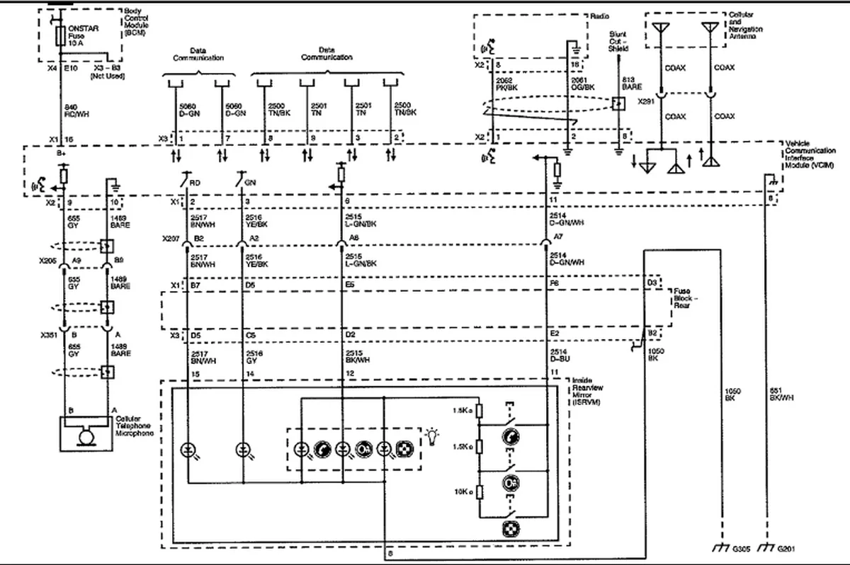
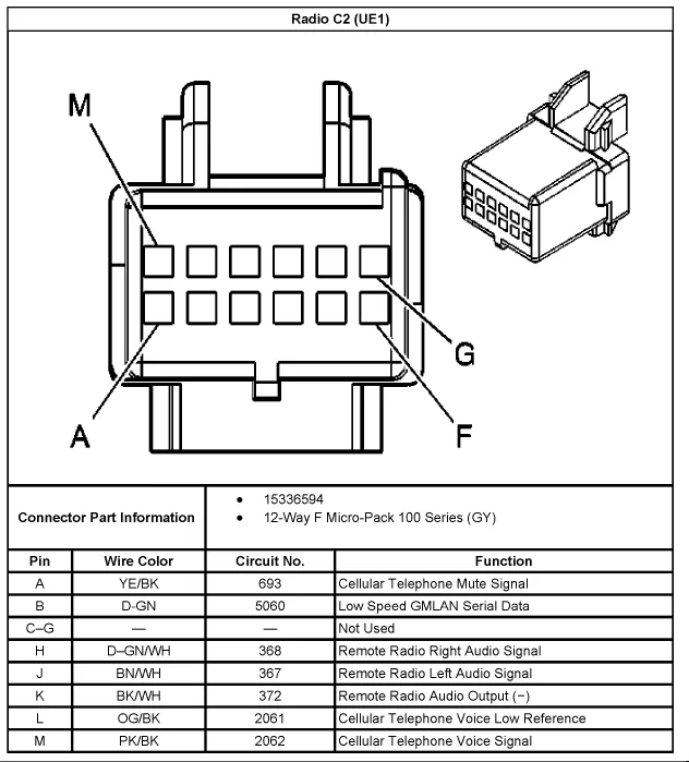
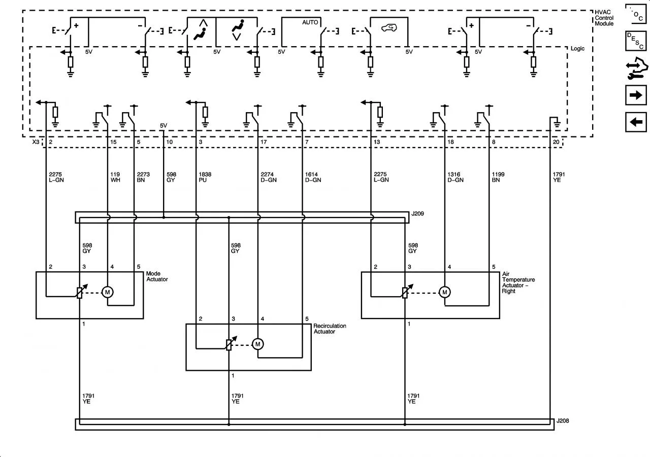
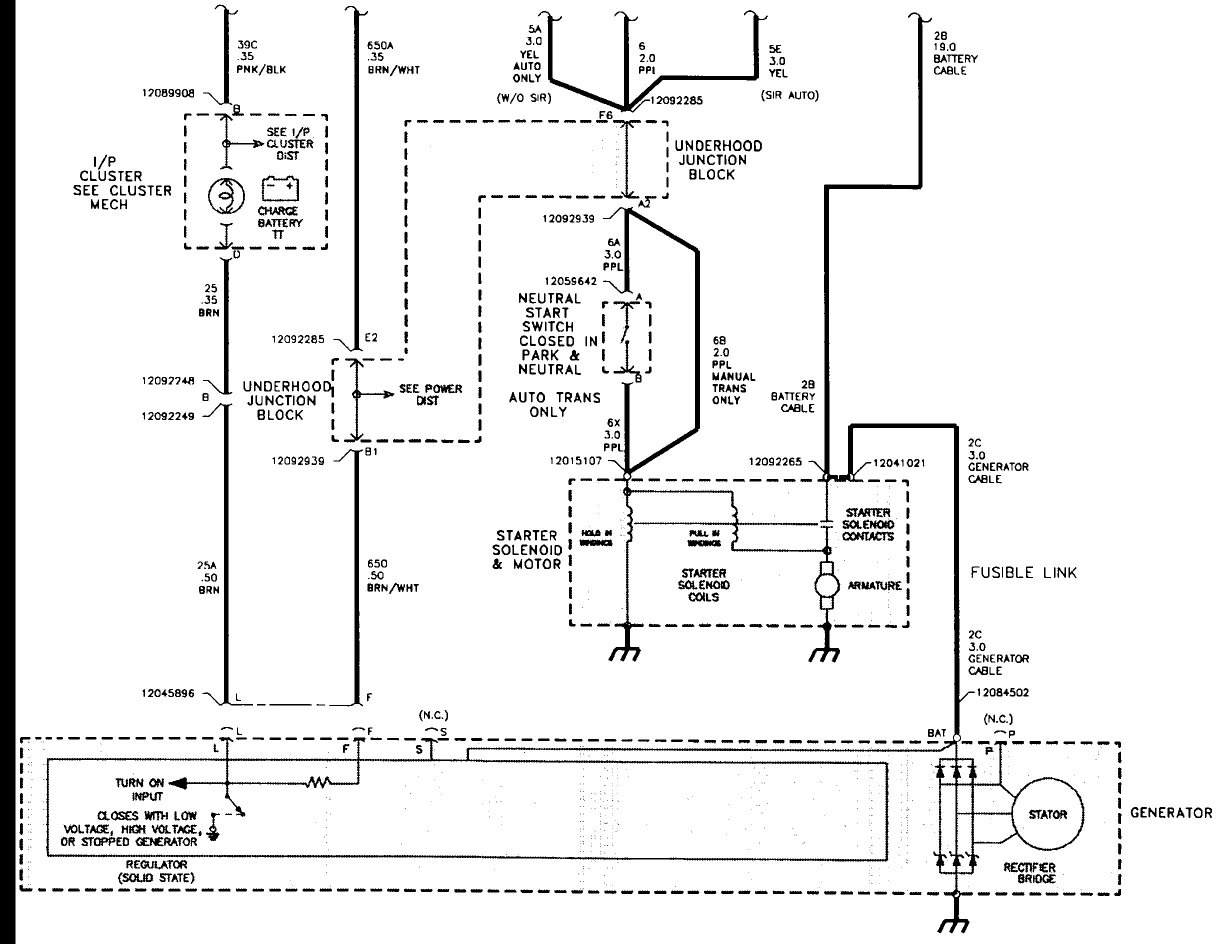
2006 Saturn Vue Wiring Diagram

The 2006 Saturn Vue wiring diagram is an essential tool for anyone looking to troubleshoot or repair electrical problems in their vehicle. Whether you’re a professional mechanic or a DIY enthusiast, understanding the wiring diagram can save you time and money and ensure that you have a safe and reliable vehicle.

What is a Wiring Diagram?

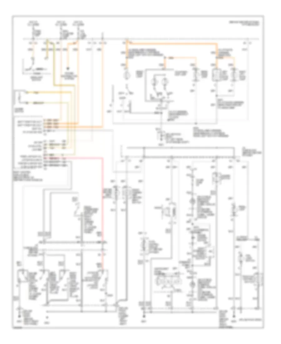
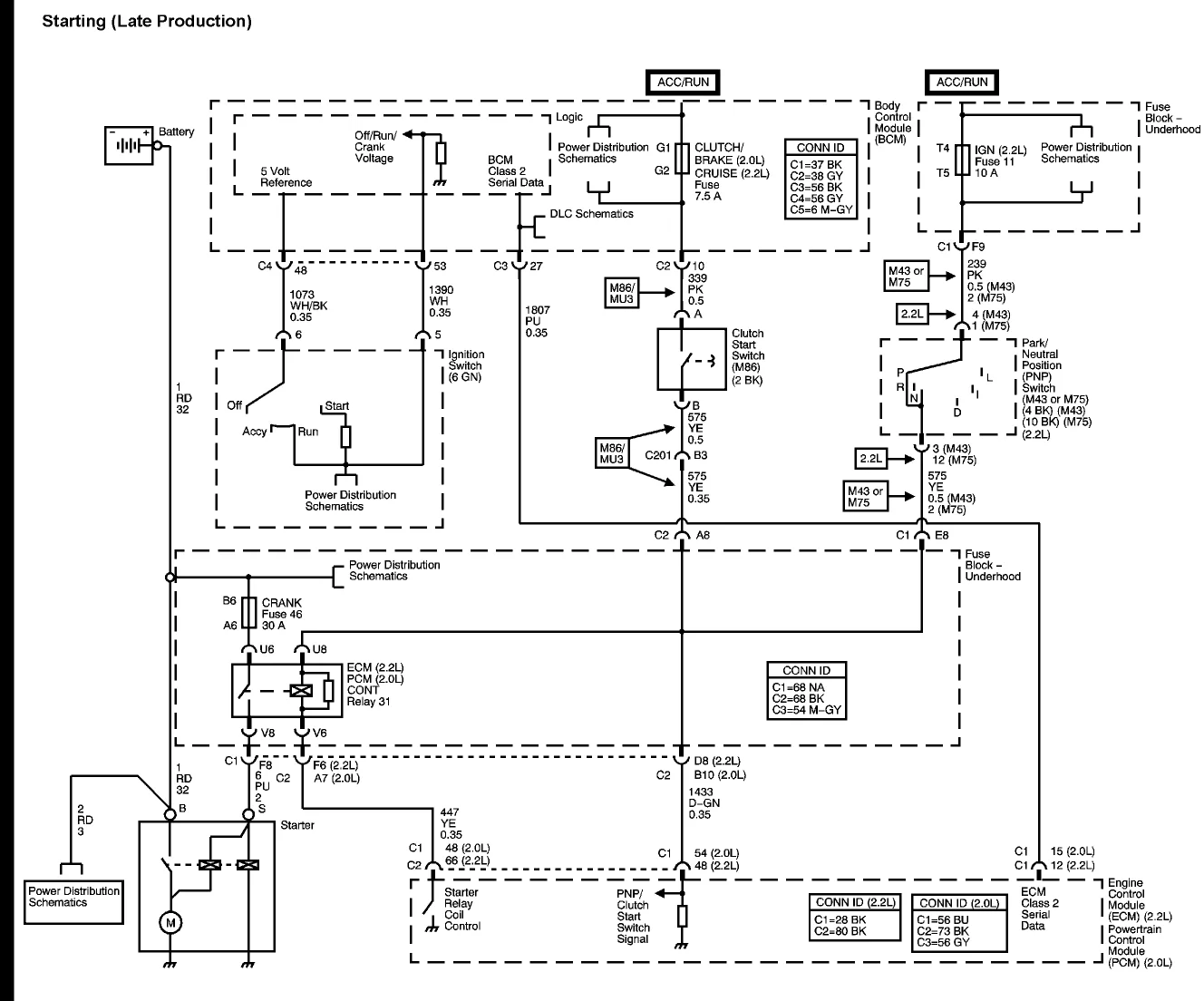
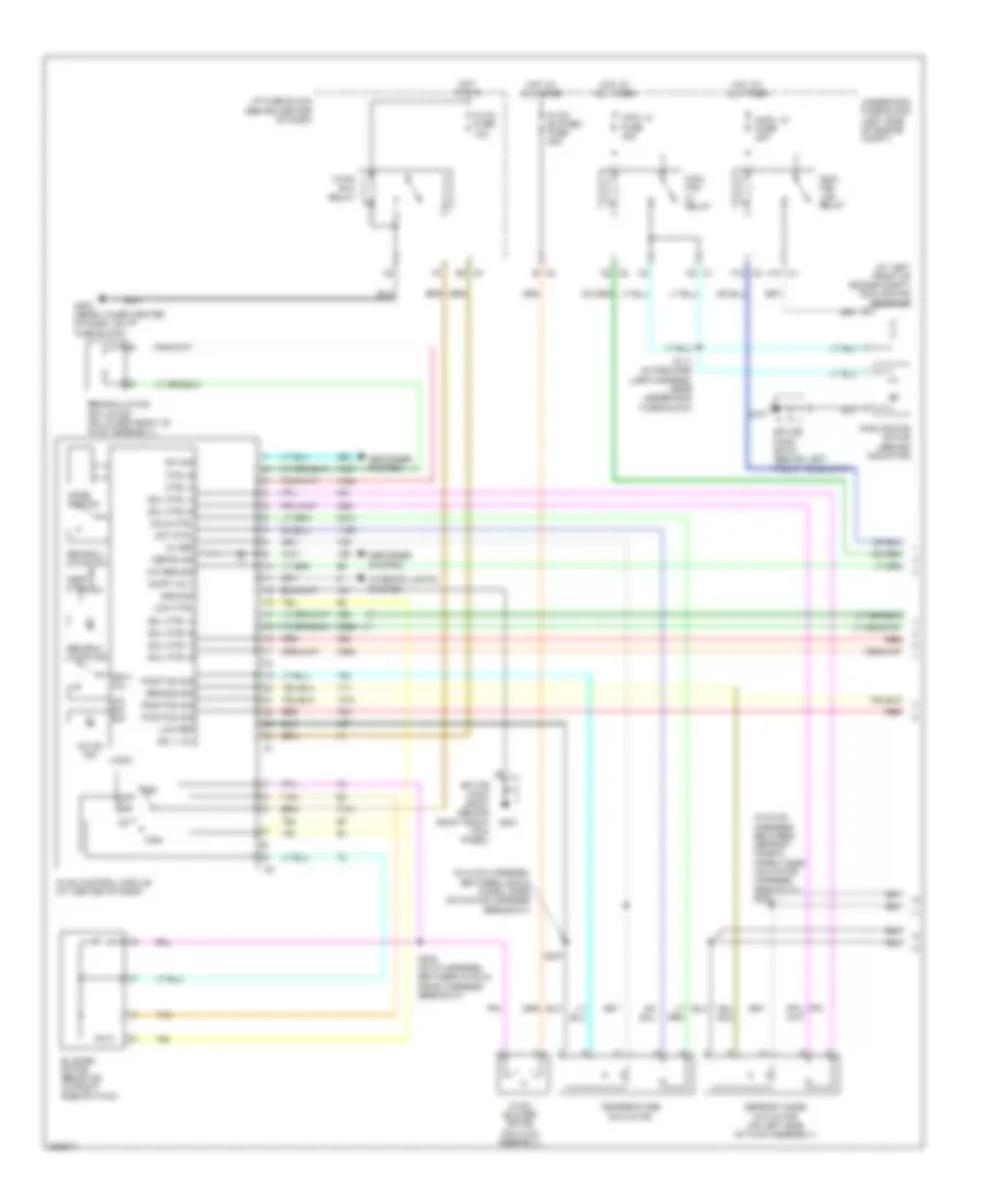
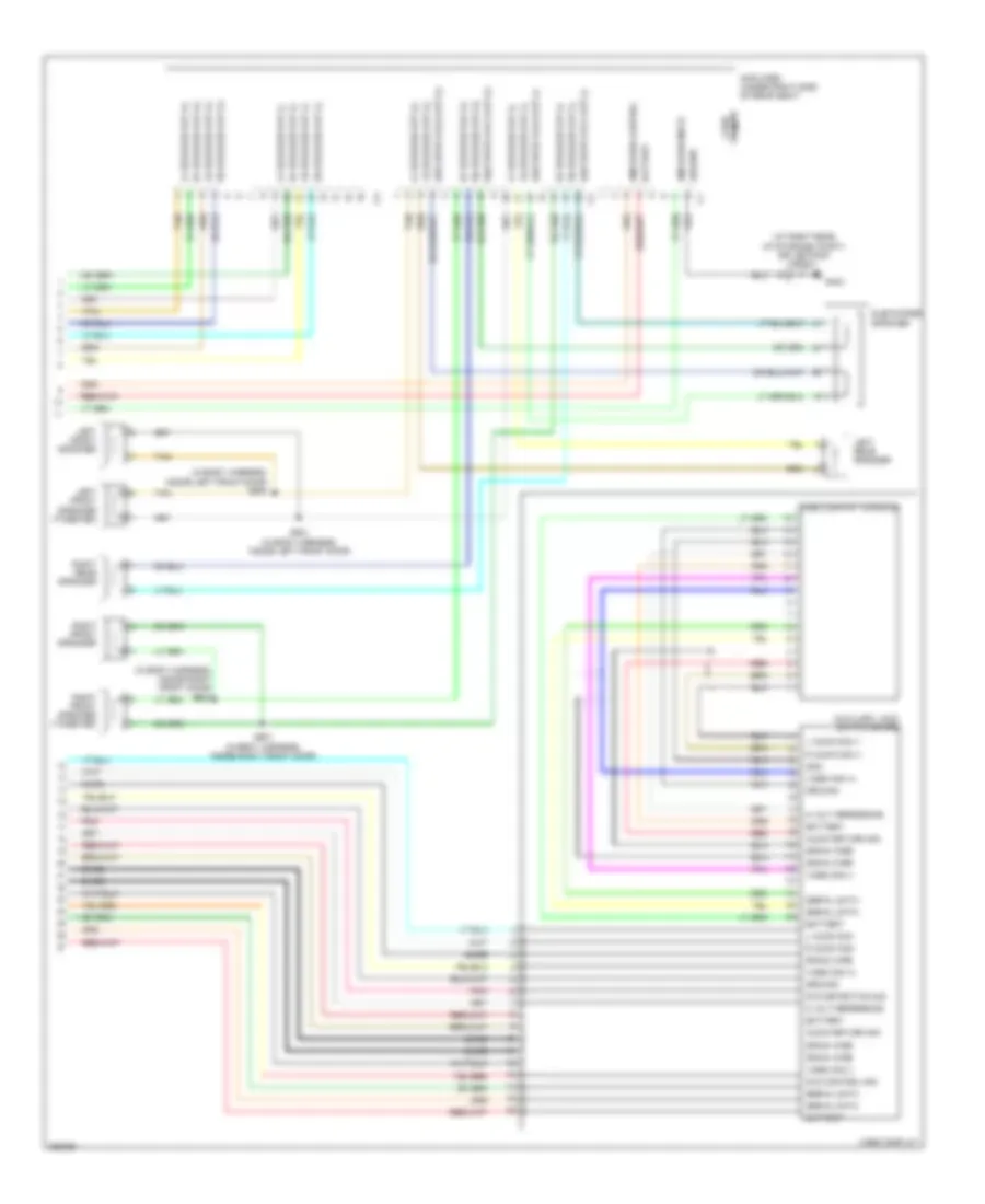
A wiring diagram is a visual representation of the electrical connections and components in a vehicle. It shows how the wires are connected and where they go, as well as the location of each component. Wiring diagrams are used to diagnose and repair electrical problems, such as a malfunctioning stereo or a dead battery.

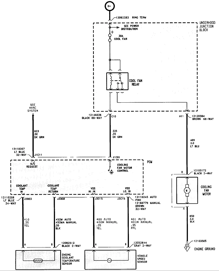
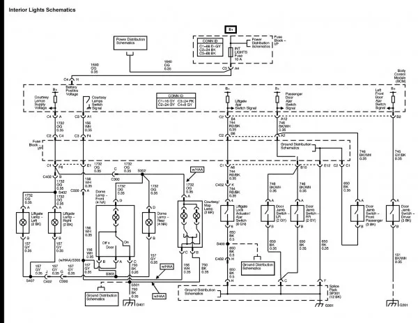
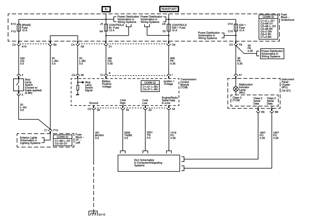
The wiring diagram is typically organized by system, including the engine, transmission, and lighting systems. Each system is represented by a series of diagrams that show the specific components and their connections. The diagrams are typically color-coded to help identify the wires and their functions.

When reading a wiring diagram, it’s important to have a basic understanding of electrical principles and the function of each component. It’s also important to follow safety procedures, such as disconnecting the battery and wearing protective gear, when working on electrical systems.

The 2006 Saturn Vue Wiring Diagram

The 2006 Saturn Vue wiring diagram is divided into several sections, each covering a different system. These sections include:

  1. Engine Control
  2. Transmission Control
  3. Body Control
  4. Chassis Control
  5. Lighting
  6. Power Distribution

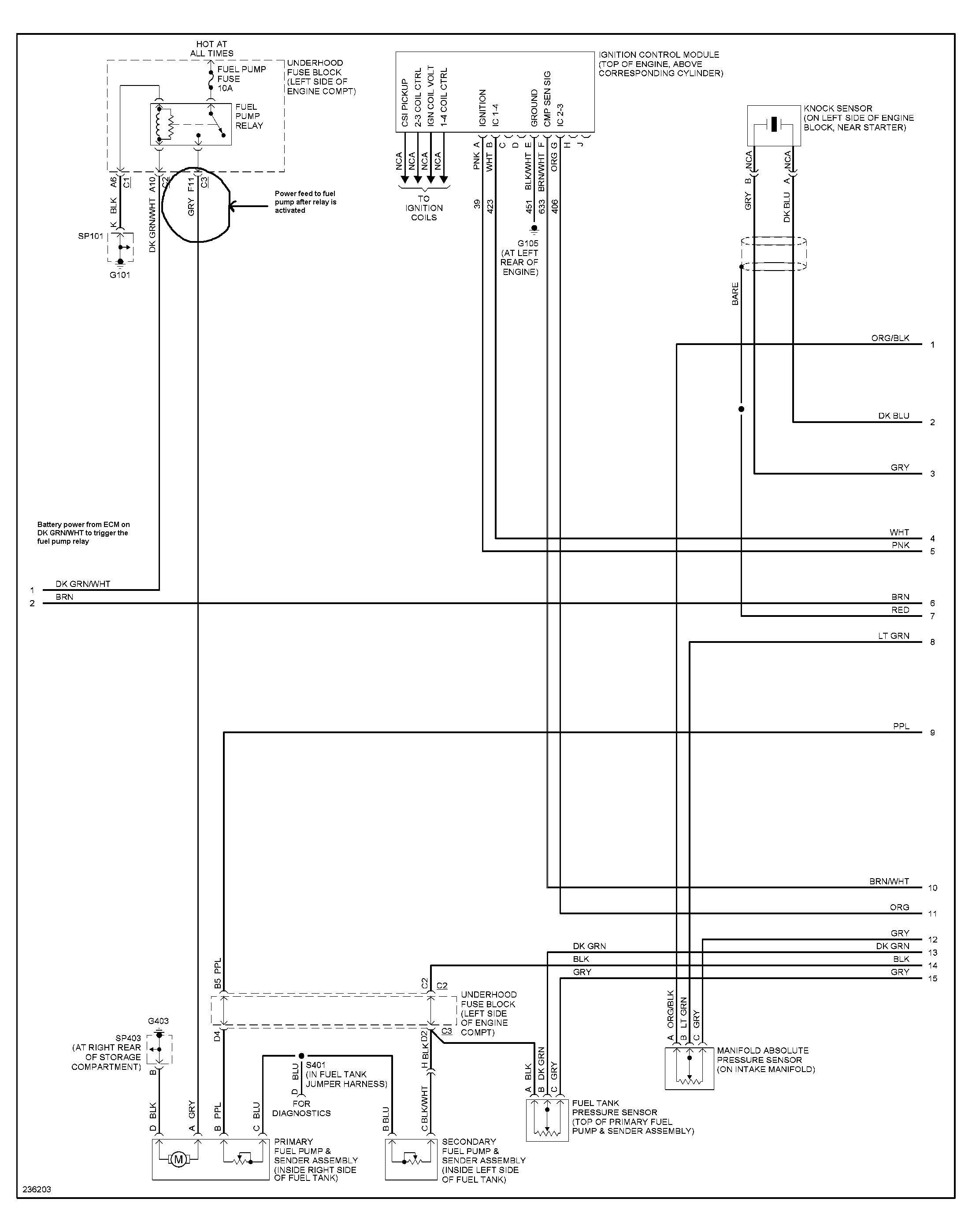
Each section contains multiple diagrams that show the various components and their connections. For example, the engine control section includes diagrams for the ignition system, fuel system, and emissions control system.

The wiring diagram also includes color codes for the wires, which are essential for identifying the correct wire and its function. The color codes are typically listed in a legend at the beginning of each section.

Using the 2006 Saturn Vue Wiring Diagram

Before using the wiring diagram, it’s important to identify the system that’s causing the problem. This can often be done by testing the components and checking for loose or damaged wires.

Once you’ve identified the system, you can use the wiring diagram to locate the specific component and check its connections. This may involve tracing the wires or using a multimeter to test for voltage and continuity.

When working with electrical systems, it’s important to follow safety procedures, such as disconnecting the battery and wearing protective gear. It’s also important to use the correct tools and equipment, such as a multimeter and wire strippers.

FAQ

What is a wiring diagram?

A wiring diagram is a visual representation of the electrical connections and components in a vehicle. It shows how the wires are connected and where they go, as well as the location of each component.

Why is a wiring diagram important?

A wiring diagram is important for diagnosing and repairing electrical problems in a vehicle. It can save time and money by helping to identify the problem and locate the specific component that needs to be repaired or replaced.

How do I read a wiring diagram?

To read a wiring diagram, it’s important to have a basic understanding of electrical principles and the function of each component. You should also follow safety procedures and use the correct tools and equipment.

What should I do if I have an electrical problem in my vehicle?

If you have an electrical problem in your vehicle, you should first identify the system that’s causing the problem. This can often be done by testing the components and checking for loose or damaged wires. Once you’ve identified the system, you can use the wiring diagram to locate the specific component and check its connections.

What safety procedures should I follow when working with electrical systems?

When working with electrical systems, it’s important to follow safety procedures, such as disconnecting the battery and wearing protective gear. You should also use the correct tools and equipment, such as a multimeter and wire strippers.

Color Codes
Color Function
Red Power
Black Ground
Yellow Accessory
Green Switched Power
Blue Antenna