1UZFE Wiring Diagram: The Ultimate Guide

Are you looking for a comprehensive guide on the 1UZFE wiring diagram? Look no further. In this article, you will learn everything you need to know about the 1UZFE engine, including its wiring diagram. Whether you’re an auto enthusiast, a mechanic, or a car owner, this guide is for you. Read on to find out more.

What is the 1UZFE Engine?

The 1UZFE is a highly sought-after engine produced by Toyota Motor Corporation. It’s a DOHC V8 engine with 32 valves, featuring electronic fuel injection (EFI). It was first introduced in the Lexus LS 400 in 1989 and has since been used in other models such as the Toyota Crown and the Toyota Soarer. The engine has a displacement of 4.0L and produces up to 290 horsepower and 300 lb-ft of torque.

The 1UZFE engine is known for its durability, reliability, and performance. It’s highly tunable and can be modified to produce even more power. It’s also a popular engine for engine swaps, especially in older cars like the Toyota Supra, Toyota Celica, and Mazda Miata. But for all these modifications and swaps, you need to understand the wiring diagram of the 1UZFE engine.

Understanding the 1UZFE Wiring Diagram

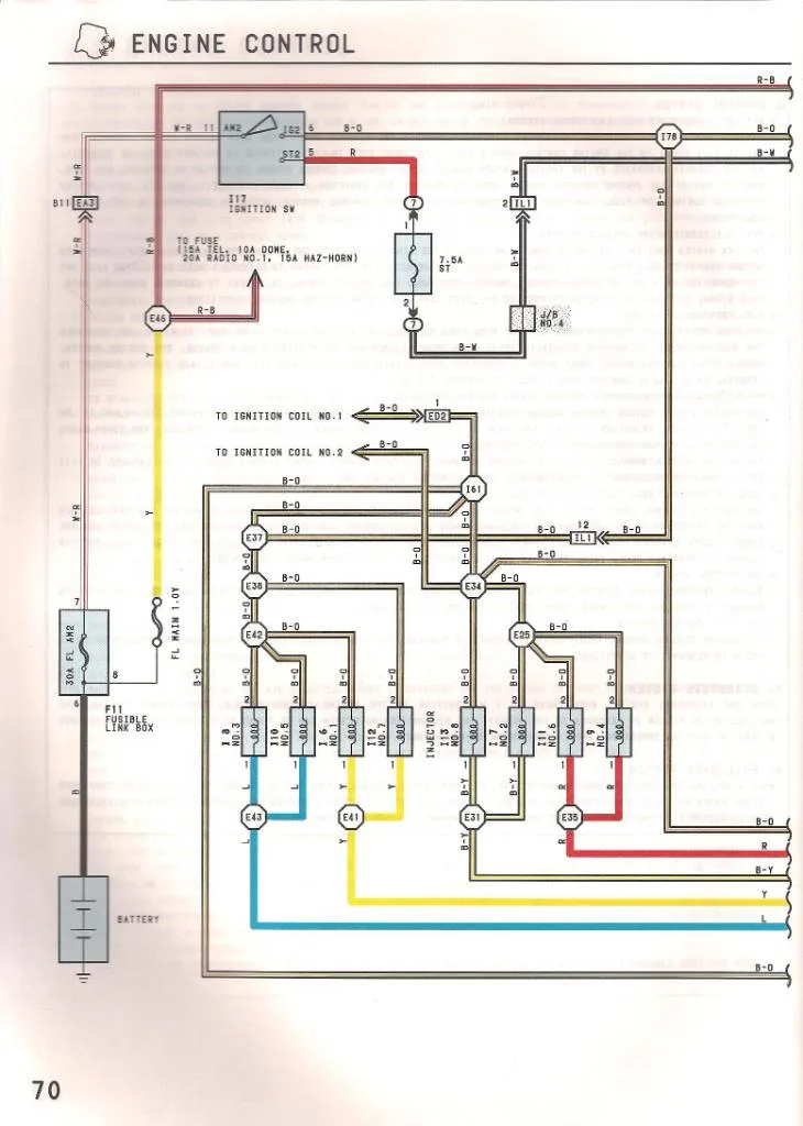
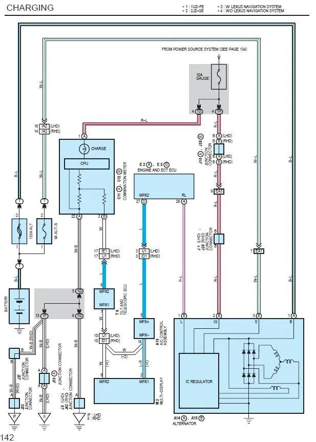
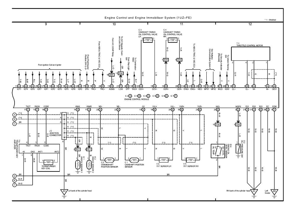
The wiring diagram of the 1UZFE engine is a complex diagram that shows the electrical connections between various components of the engine, including sensors, injectors, ignition coils, and more. It’s important to understand this diagram to diagnose any electrical problems in the engine and to modify the engine without damaging it.

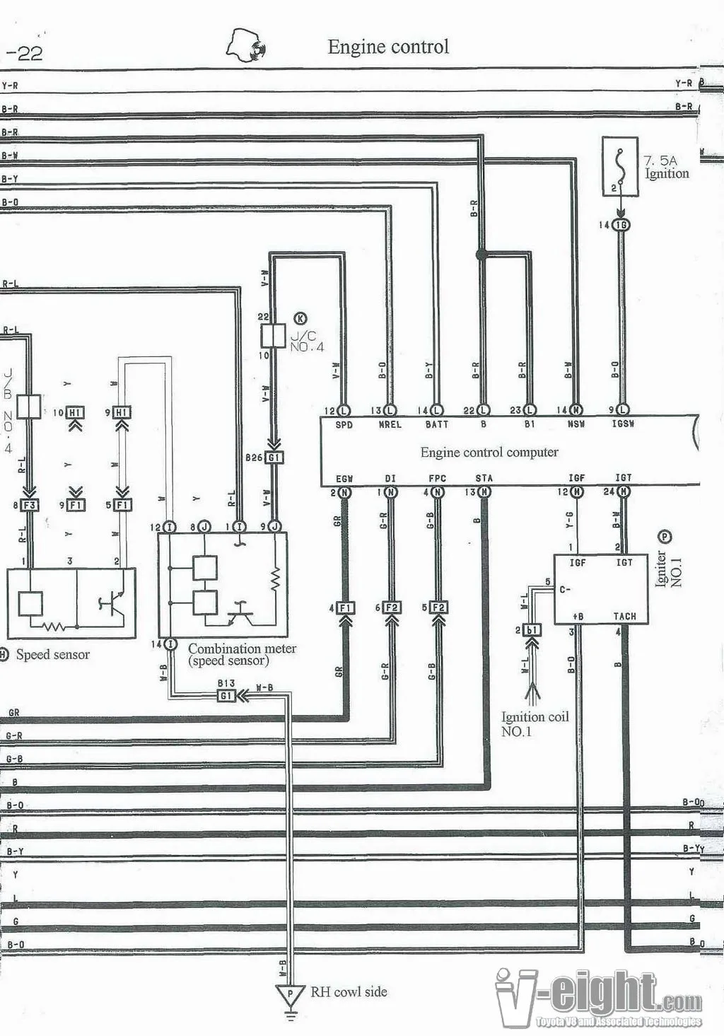
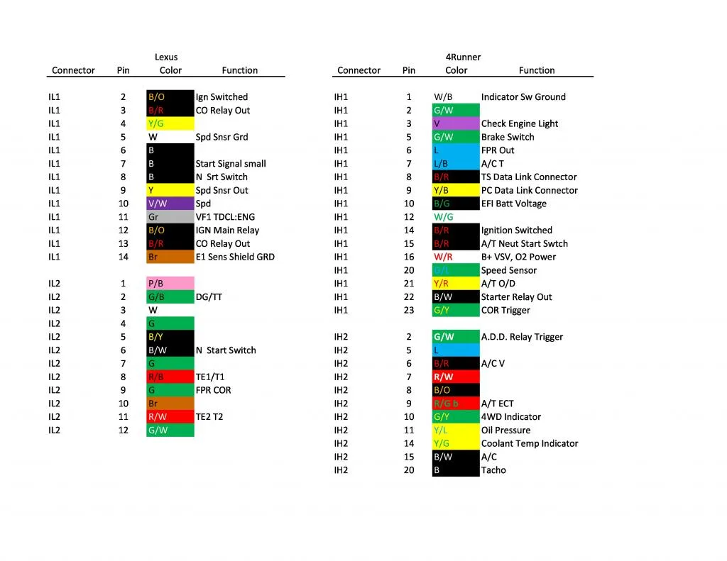
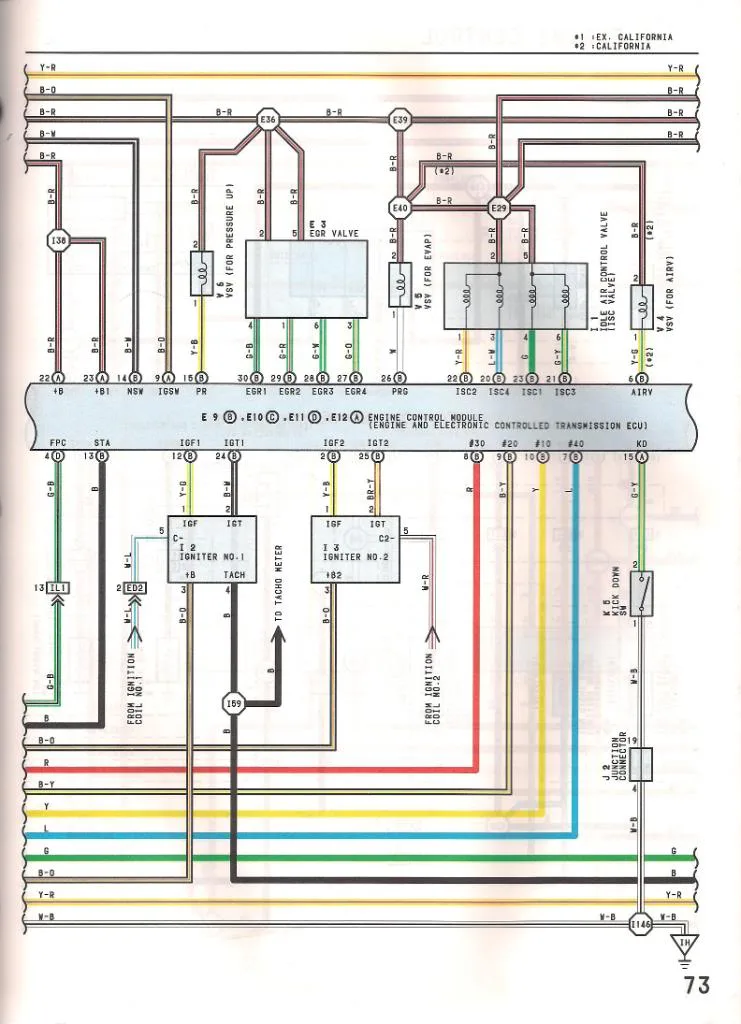
The diagram consists of various components, including the engine control module (ECM), sensors, actuators, and other electrical components. These components are interconnected through wires and connectors, and the functions of each component are controlled by the ECM. The wiring diagram shows the color codes of the wires, the pinouts of the connectors, and the routing of the wires throughout the engine.

The ECM

The engine control module (ECM) is the brain of the engine. It’s responsible for controlling various functions of the engine, such as fuel injection, ignition timing, and emissions. The ECM receives signals from various sensors, processes these signals, and sends output signals to various actuators to control the engine’s functions.

The wiring diagram shows the pinouts of the ECM connector and the functions of each pin. It also shows the wiring connections between the ECM and various sensors and actuators.

The Sensors

The sensors in the 1UZFE engine are crucial for its performance and operation. These sensors include the crankshaft position sensor, camshaft position sensor, coolant temperature sensor, air flow meter, oxygen sensor, and more. The wiring diagram shows the connections between these sensors and the ECM. It also shows the color codes of the wires and the pinouts of the connectors.

The Actuators

The actuators in the 1UZFE engine include the injectors, ignition coils, idle air control valve, and more. These actuators are controlled by the signals from the ECM. The wiring diagram shows the connections between these actuators and the ECM. It also shows the color codes of the wires and the pinouts of the connectors.

FAQ About the 1UZFE Wiring Diagram

What is the use of the 1UZFE wiring diagram?

The 1UZFE wiring diagram is used to diagnose electrical problems in the engine and to modify the engine without damaging it. It shows the connections between various components of the engine, including sensors, actuators, and the ECM. It also shows the color codes of the wires and the pinouts of the connectors.

How can I get a 1UZFE wiring diagram?

The 1UZFE wiring diagram can be obtained from various sources, including automotive repair manuals, online forums, and Toyota service centers. You can also find aftermarket wiring diagrams from companies that specialize in engine swaps and modifications.

How do I read a 1UZFE wiring diagram?

Reading the 1UZFE wiring diagram requires some knowledge of electrical circuits and symbols. You should start by identifying the components shown in the diagram and their connections. You should also understand the color codes of the wires and the pinouts of the connectors. Once you understand these basics, you can diagnose electrical problems and modify the engine without damaging it.

What is the importance of understanding the 1UZFE wiring diagram?

Understanding the 1UZFE wiring diagram is crucial for any modifications or swaps involving the engine. It allows you to diagnose electrical problems, modify the engine without damaging it, and tune it for maximum performance. It’s also important for mechanics and technicians who work on the engine, as it allows them to troubleshoot any problems quickly and efficiently.

Can I modify the 1UZFE engine without understanding its wiring diagram?

Modifying the 1UZFE engine without understanding its wiring diagram can be dangerous and can damage the engine. Electrical problems can arise from incorrect wiring or connections, and these problems can cause the engine to malfunction or fail. It’s essential to understand the wiring diagram before modifying the engine to ensure its durability and reliability.

Conclusion

The 1UZFE wiring diagram is a critical component of the engine’s operation and maintenance. Understanding this diagram is crucial for any modifications or swaps involving the engine. By following the guidelines in this article, you can understand the wiring diagram and modify the engine without damaging it. Whether you’re an auto enthusiast, a mechanic, or a car owner, this guide is for you.