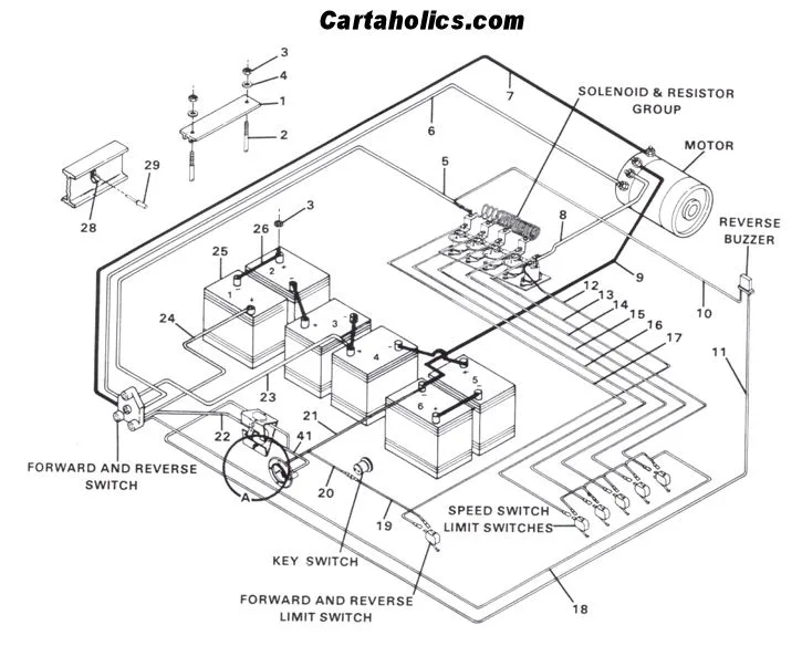
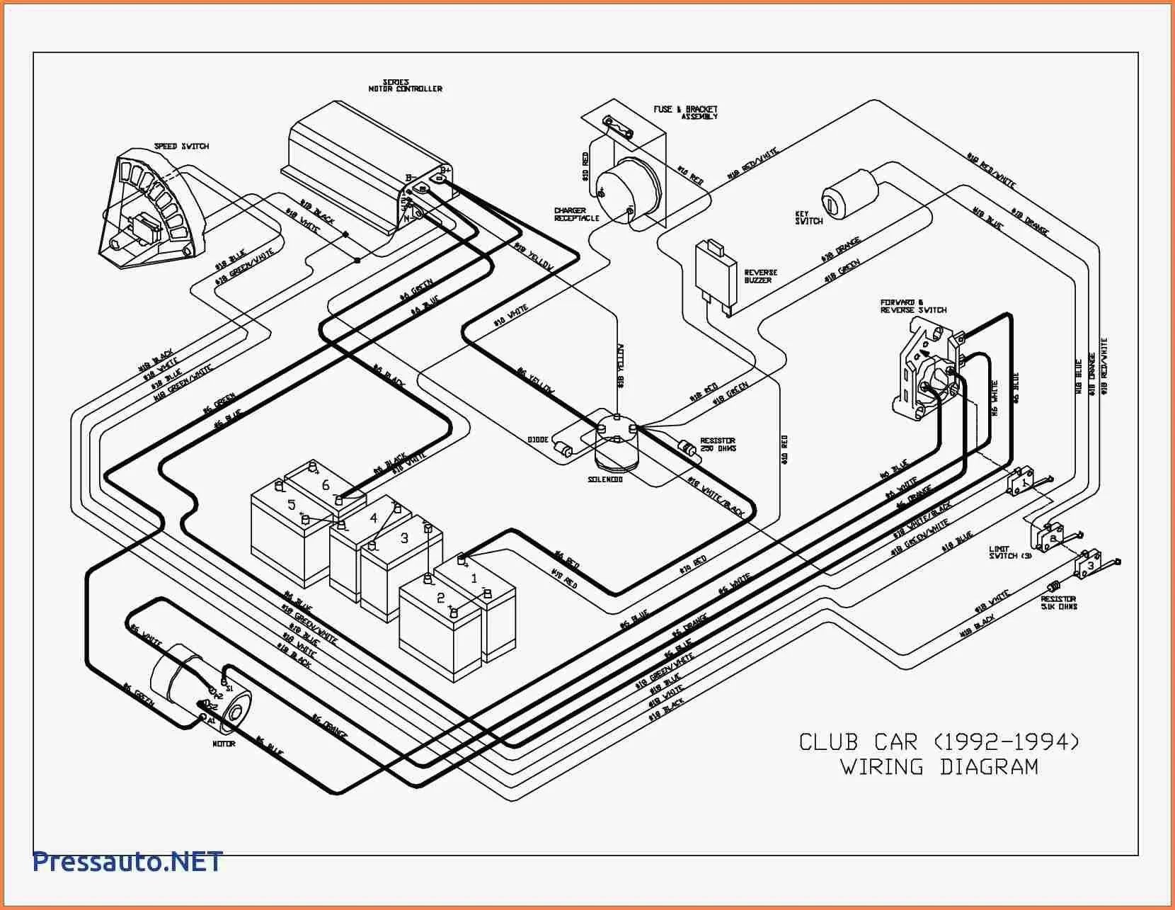
If you own or are interested in purchasing a 1982 Club Car DS, it is important to understand the wiring diagram. This diagram shows how the electrical components are connected and helps to troubleshoot any issues that may arise. In this article, we will discuss the 1982 Club Car DS Wiring Diagram and provide a detailed breakdown.
What is the 1982 Club Car DS Wiring Diagram?
The 1982 Club Car DS Wiring Diagram is a schematic representation of the electrical system in a 1982 Club Car DS. It shows the various components and how they are connected in the circuit. The diagram is essential for troubleshooting any electrical issues that may arise with the vehicle.
The diagram includes various components such as the battery, solenoid, F/R switch, motor, and controller. Each of these components plays a vital role in the functioning of the vehicle and must be connected correctly for the vehicle to operate efficiently.
Understanding the 1982 Club Car DS Wiring Diagram
The 1982 Club Car DS Wiring Diagram may seem complicated at first glance, but it is relatively easy to understand once you break it down. There are various components, and each of these components has specific wiring instructions that must be followed.
The battery, for example, is the heart of the electrical system. The diagram shows how the battery is connected to the solenoid and controller. The solenoid is a switch that controls the power to the motor, and the controller regulates the power to the motor.
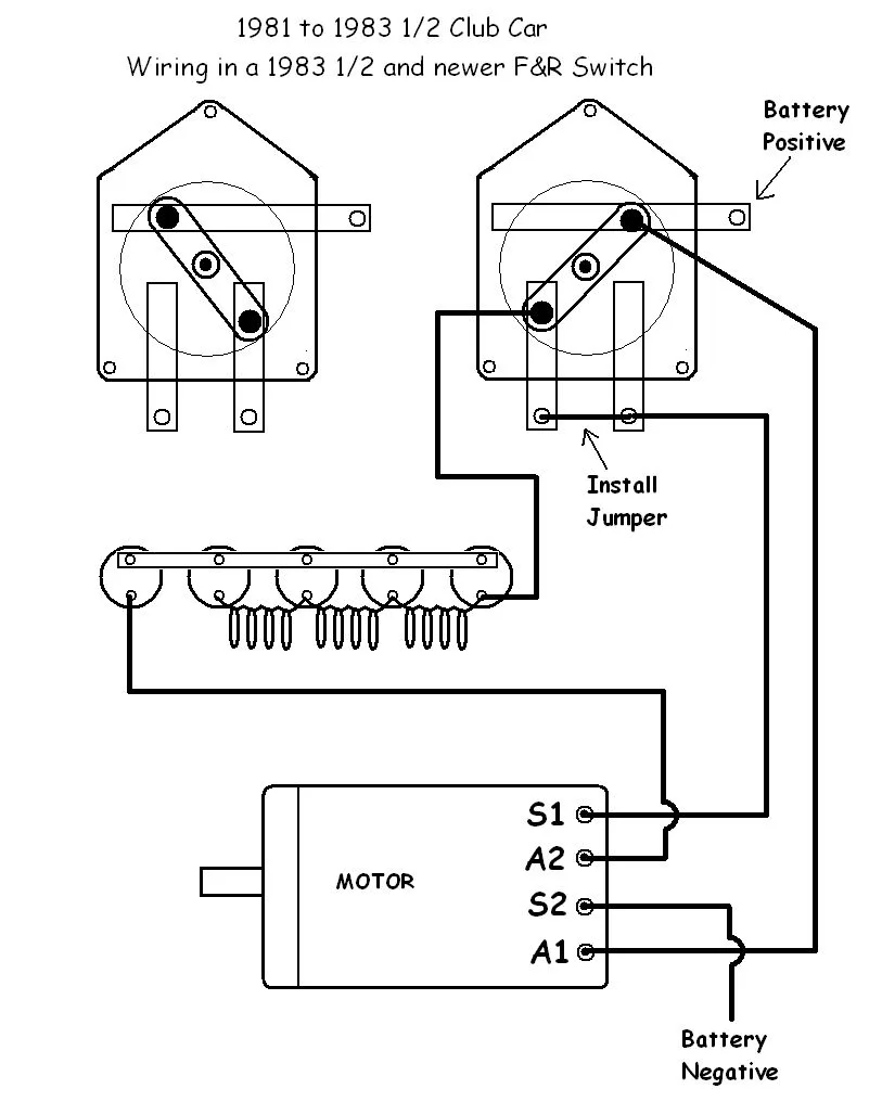
The F/R switch is a critical component as it controls the direction of the vehicle. The diagram shows how the switch is connected to the motor and allows the vehicle to move forward or backward. The motor itself is connected to the controller, and the controller regulates the power to the motor.
Battery
The battery is the source of power for the electrical system. It is a 36-volt system, and the batteries are connected in a series to create the necessary voltage. The diagram shows how the batteries are connected to the solenoid and controller. It is essential to ensure that the batteries are connected correctly to avoid any damage to the system.
When connecting the batteries, you must ensure that the positive terminal of one battery is connected to the negative terminal of the following battery. This creates a closed circuit and allows the necessary voltage to flow through the system.
Solenoid
The solenoid is a switch that controls the power to the motor. When the F/R switch is engaged, the solenoid allows the voltage to flow from the battery to the controller and on to the motor. The solenoid is connected to the battery and F/R switch.
When wiring the solenoid, you must ensure that the terminals are correctly connected. The diagram shows how the solenoid is connected to the battery and F/R switch. It is essential to follow these instructions carefully to ensure that the solenoid functions correctly.
F/R Switch
The F/R switch controls the direction of the vehicle. When the switch is engaged, it allows the voltage to flow to the motor, either in the forward or reverse direction. The switch is connected to the solenoid and motor.
The wiring for the F/R switch can be challenging, so it is essential to follow the instructions carefully. The diagram shows how the switch is wired to the solenoid and motor. It is important to ensure that the wiring is correct to avoid any issues with the switch.
Motor
The motor is the component that provides the power to drive the vehicle. It is connected to the controller, which regulates the power. The motor is connected to the F/R switch and solenoid.
It is essential to wire the motor correctly to avoid any issues with the vehicle’s operation. The diagram shows how the motor is connected to the F/R switch and solenoid. It is important to follow the instructions carefully to ensure that the wiring is correct.
Controller
The controller regulates the power to the motor. It is connected to the solenoid and motor and receives the necessary input from the F/R switch. The controller plays a vital role in the vehicle’s operation and must be wired correctly.
The diagram shows how the controller is wired to the solenoid, motor, and F/R switch. It is important to follow the instructions carefully to avoid any issues with the controller.
FAQ
What happens if the wiring is incorrect?
If the wiring is incorrect, the vehicle may not operate correctly. There may be issues with the motor, solenoid, or controller, which can lead to problems with the vehicle’s performance.
Can I troubleshoot electrical issues without the wiring diagram?
It is possible to troubleshoot electrical issues without the wiring diagram, but it can be challenging. The diagram provides a visual representation of the electrical system, making it easier to identify the problem.
Why is it essential to follow the wiring instructions carefully?
It is essential to follow the wiring instructions carefully to avoid any issues with the vehicle’s operation. The wiring instructions are specific to the 1982 Club Car DS, and any deviation from these instructions can lead to problems.
Where can I find the wiring diagram for a 1982 Club Car DS?
The wiring diagram for a 1982 Club Car DS can be found in the vehicle’s user manual or online. There are several resources available online that provide the diagram, including the Club Car website.
Conclusion
The 1982 Club Car DS Wiring Diagram is a crucial component for the vehicle’s operation. Understanding the diagram and following the wiring instructions carefully can help to avoid any issues with the vehicle’s performance. The diagram is essential for troubleshooting any electrical issues that may arise, and it is worth taking the time to understand it fully.