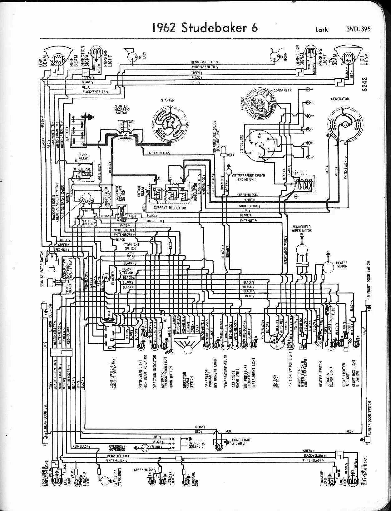
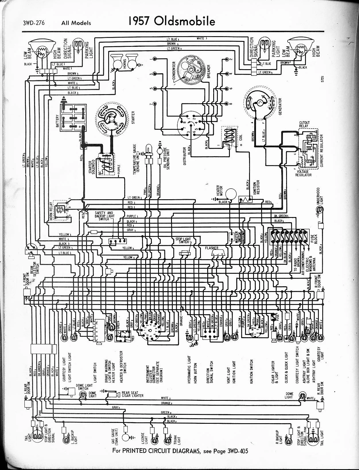
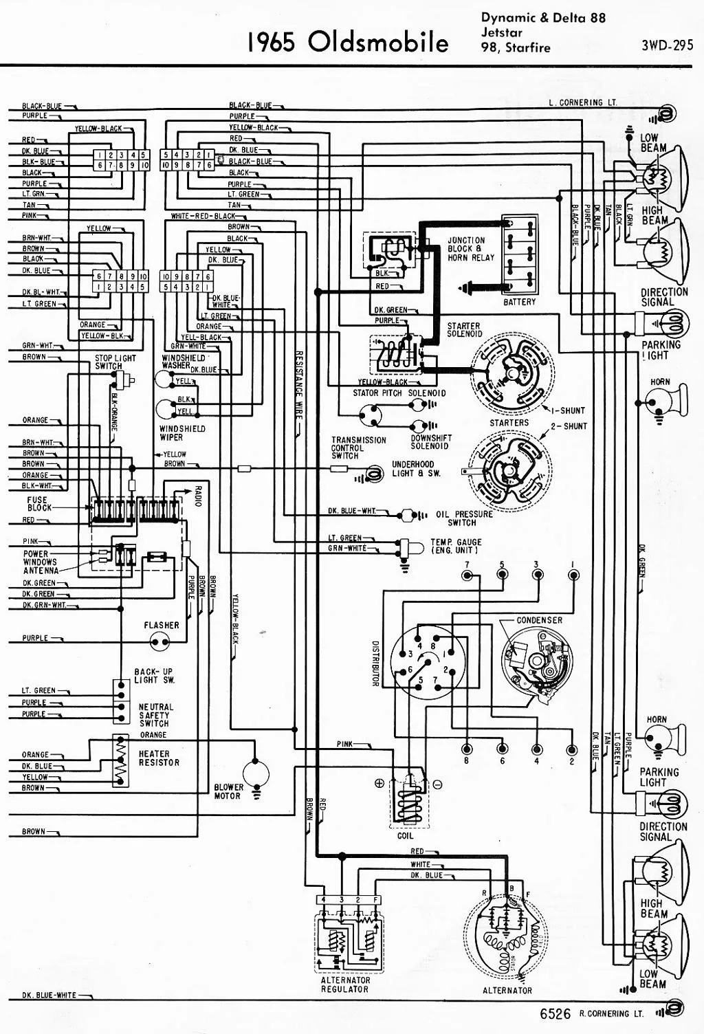
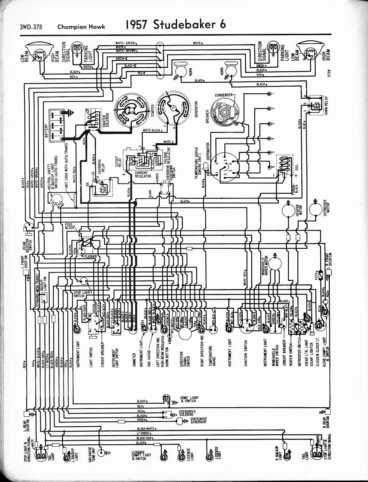
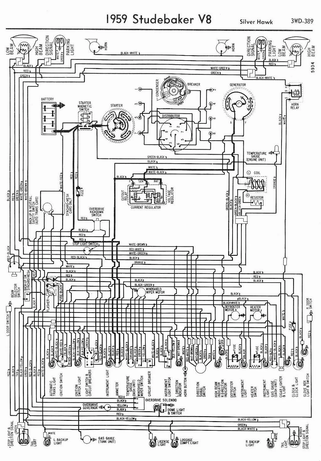
1964 Chevy Impala Wiring Diagram: A Comprehensive Guide

Are you having trouble with the wiring of your 1964 Chevy Impala? If so, then this article is for you. In this guide, we will provide you with a comprehensive wiring diagram for your Chevy Impala. We understand that wiring can be complicated and confusing, but we are here to help you every step of the way.

What is a Wiring Diagram?

Before we dive into the wiring diagram for your 1964 Chevy Impala, let’s first understand what a wiring diagram is. A wiring diagram is a visual representation of the electrical components and connections in a vehicle. It shows how each component is connected with others and how they work together to make the vehicle functional.

Wiring diagrams are essential tools for mechanics and car enthusiasts as they provide a clear understanding of the electrical system of the vehicle. By having a wiring diagram, you can identify the cause of any electrical issue and fix it accordingly.

Why Do You Need a Wiring Diagram for Your 1964 Chevy Impala?

As mentioned earlier, wiring can be complicated and confusing. With a wiring diagram, you can easily understand the electrical components and connections in your Chevy Impala. It allows you to identify any faulty wiring or components and fix them before they cause any further damage.

Having a wiring diagram also helps in the installation of new components or modifications. You can refer to the wiring diagram to ensure that the new components are installed correctly, and the wiring connections are in the right place.

The Wiring Diagram for Your 1964 Chevy Impala

Now, let’s dive into the main section of this article – the wiring diagram for your 1964 Chevy Impala. The diagram is divided into several sections, including:

Section Description
Front Section Includes the headlights, horns, and battery connections.
Instrument Panel Section Includes the gauges, radio, and heater controls.
Engine Section Includes the starter, ignition, and charging systems.
Rear Section Includes the tail lights, brake lights, and fuel gauge.

Front Section

The front section of the wiring diagram includes the headlights, horns, and battery connections. The diagram shows the connections from the battery to the headlight switch and horn relay. It also shows the connections from the headlight switch to the headlights and the horn relay to the horns.

The wiring diagram also includes the connections for the voltage regulator and alternator. The voltage regulator is responsible for regulating the voltage output from the alternator to ensure that the battery is charged correctly.

Lastly, the diagram shows the ground connections for the headlights, horn, and battery. Ground connections are essential to ensure that the electrical system works correctly.

Instrument Panel Section

The instrument panel section of the wiring diagram includes the gauges, radio, and heater controls. The diagram shows the connections from the fuse block to the ignition switch and the connections from the ignition switch to the gauges and radio.

It also shows the connections from the radio to the speakers and the connections from the heater switch to the blower motor. The wiring diagram includes all the connections necessary to operate the gauges, radio, and heater controls.

Engine Section

The engine section of the wiring diagram includes the starter, ignition, and charging systems. The diagram shows the connections from the starter to the battery and ignition switch. It also shows the connections from the ignition switch to the coil and distributor.

The alternator connections are also shown in the engine section. The diagram shows the connections from the alternator to the voltage regulator and battery.

Rear Section

The rear section of the wiring diagram includes the tail lights, brake lights, and fuel gauge. The diagram shows the connections from the fuse block to the brake light switch and the connections from the brake light switch to the brake lights.

The wiring diagram also includes the connections for the tail lights and fuel gauge. It shows the connections from the tail light switch to the tail lights and the connections from the fuel sender to the fuel gauge.

Frequently Asked Questions

1. Can I use this wiring diagram for other years of Chevy Impala?

No, this wiring diagram is specifically for the 1964 Chevy Impala. Other years and models may have different wiring diagrams.

2. Do I need any special tools to use this wiring diagram?

No, you do not need any special tools to use this wiring diagram. However, basic knowledge of electrical systems is essential.

3. Can I modify the wiring of my Chevy Impala using this diagram?

Yes, you can modify the wiring of your Chevy Impala using this wiring diagram. However, it is essential to understand the modifications and ensure that they are implemented correctly to avoid any electrical issues.

4. Can I print this wiring diagram?

Yes, you can print this wiring diagram. However, ensure that the printer settings are set to print in landscape mode to ensure that the diagram fits on one page.

Conclusion

In conclusion, having a wiring diagram is essential for maintaining, troubleshooting, and modifying the electrical system of your 1964 Chevy Impala. The wiring diagram provided in this article covers all the electrical components and connections in your Chevy Impala. By using this wiring diagram, you can easily identify any electrical issues and fix them accordingly.

Remember to follow the wiring diagram carefully and ensure that all connections are secure and in the right place. With the right knowledge and tools, you can keep your Chevy Impala’s electrical system running smoothly.