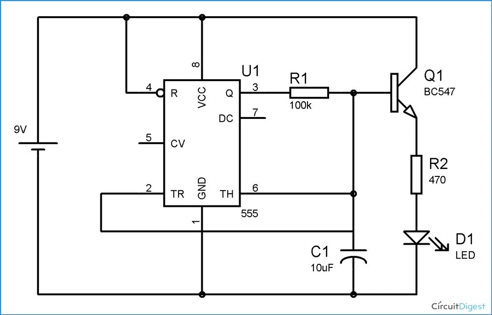
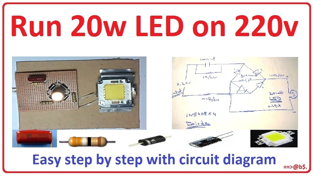
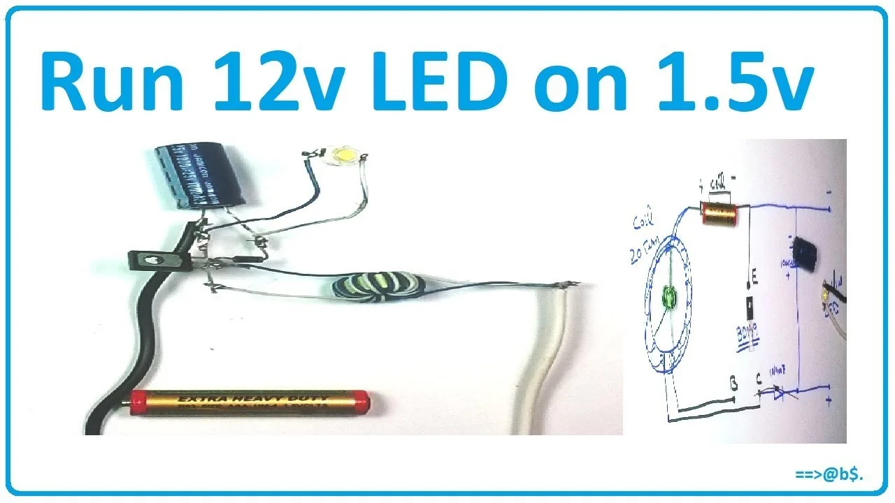
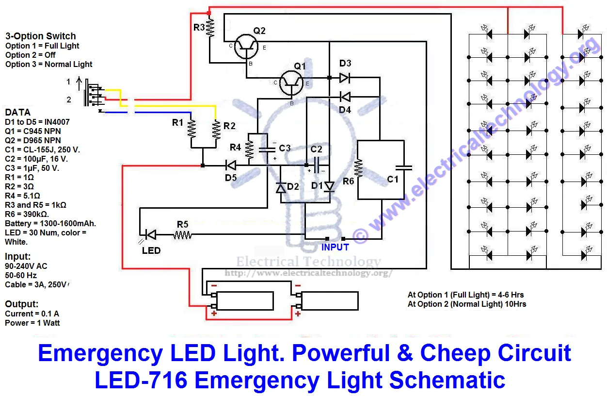
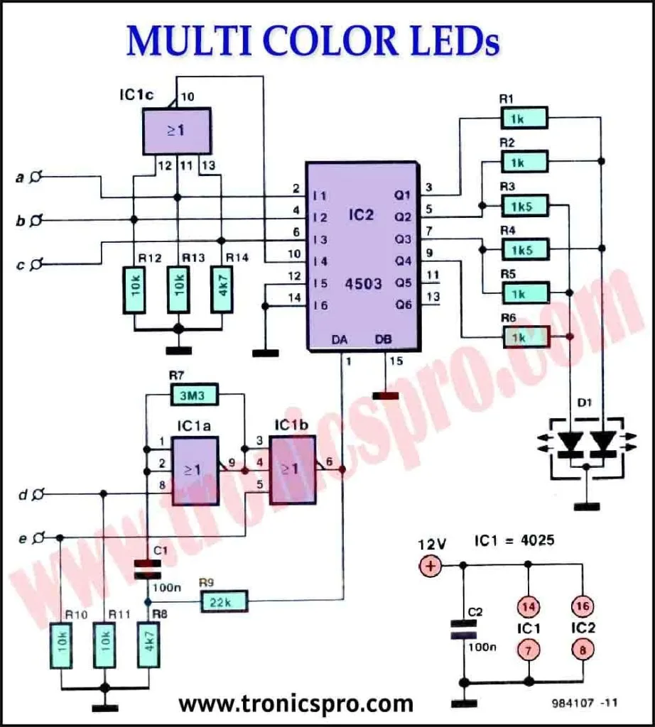
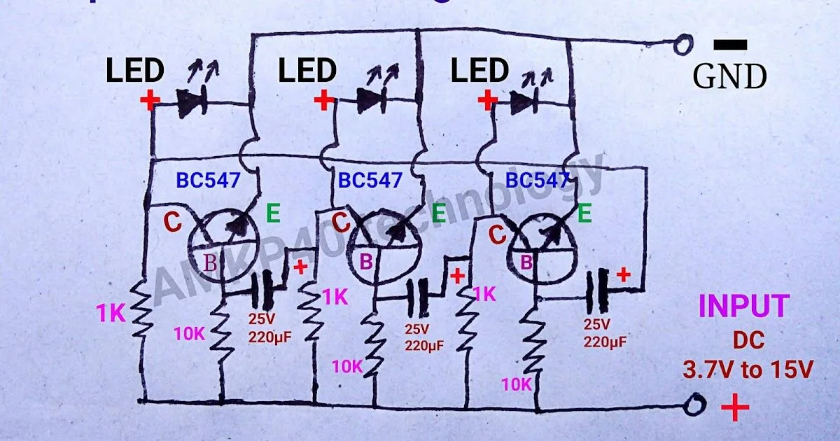
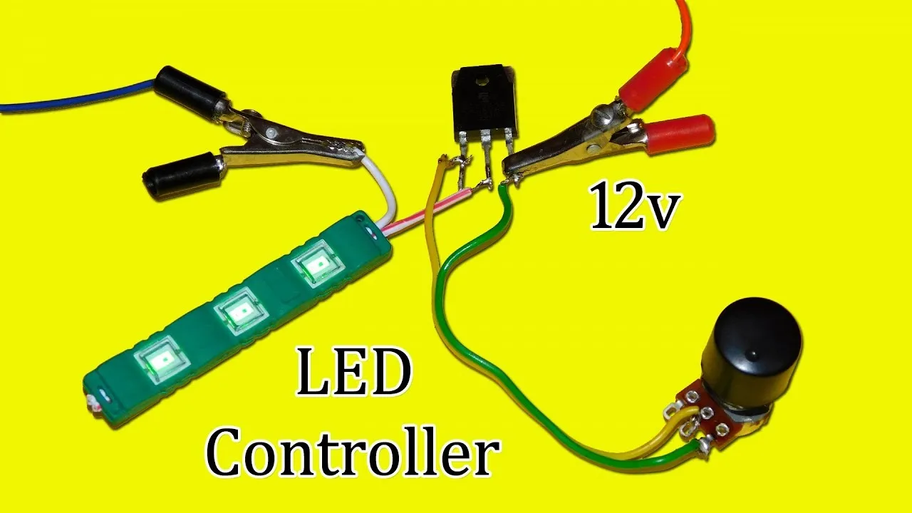
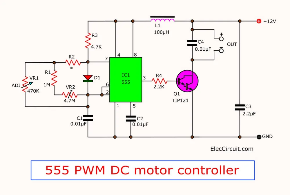
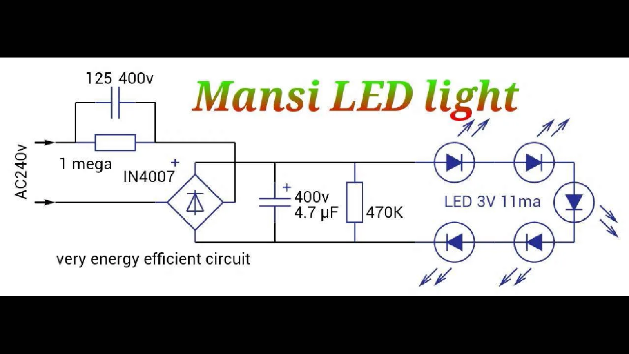
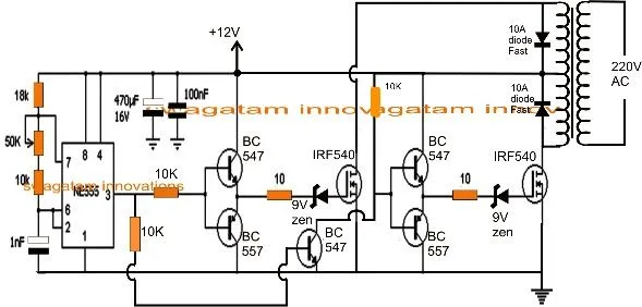
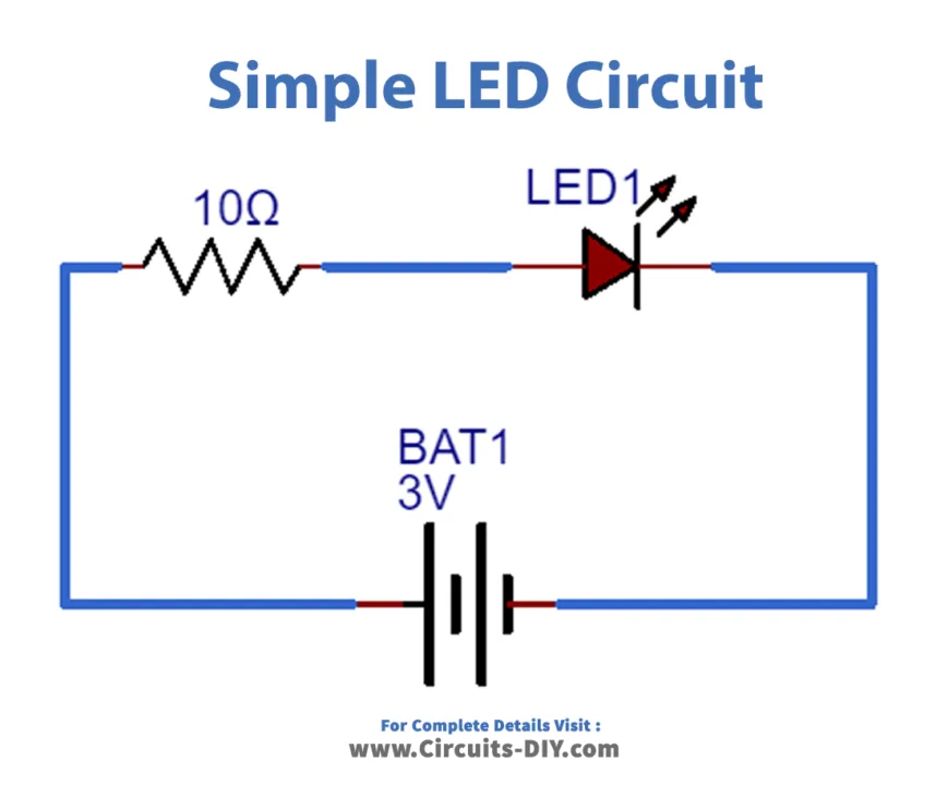
12V Led Circuit Diagram Wallpapers
Related Images
More Images
Explore Topics 1
- 98 Acura Integra Fuse Diagram
- Diagram 2005 Ford Explorer Fuse Box Diagram Only
- Wiring Diagram 1995 Buick Park Avenue
- Toyota Alphard Wiring Diagram
- 20010Jeep Grand Cherokee Fuel Wiring Diagram
- 1995 Buick Park Avenue Starter Wiring Diagram
- 1951 Chevy Fleetline Wiring Diagram
- Taurus Fan Wiring Diagram
- Cat C12Oil Pump Diagram
- True Byp Wiring Diagram
Explore Topics 2
- Diagram Of An Onion Plant
- Plymouth Voyager Wiring Diagrampressor
- Turn Signal Side Marker Lights Wiring Diagram
- Security Cable Wiring Diagram
- 1999 Ford F1510Fusible Link Diagram
- Telecaster Wiring Diagram Tbx
- Nest Thermostat Wire Diagram
- 2004 Jeep Grand Cherokee Ac Vacuum Hose Diagram
- Component Speakers To Amp Wiring Diagram
- 2003 Avalanche Fuse Box Diagram
Explore Topics 3
- 1973 Ford F1510Fuse Box Diagram
- 1996 Pathfinder Engine Diagram
- Fast Wiring Diagram
- 2004 Monte Carlo Fuse Box Diagram
- 2011Bmw X3 Fuse Diagram
- Suzuki Wagon R Rb3110Rb423 Rb413D Service Repair Manual Wiring Diagram Manual Download
- Bunker Hill Security Camera Wireless Color Security Diagram
- 1994 Ford Explorer Diagram
- Bar Diagram Math
- 2006 Bmw X5 Alternator Wiring Diagram
Explore Topics 4
- John Deere 30210Wiring Diagram
- Fuel Transfer Pump Wiring Diagram
- Q E Scooter Wire Diagram
- 1998 Chevy Silverado Ignition Wiring Diagram
- Hair Dryer Circuit Diagram
- Wiring Harness Diagram 2001 Gsxr 750
- 1988 Chevy S110Ignition Switch Wiring Diagram
- 2002 Jeep Wrangler Wiring Diagram O2
- Star Delta Wiring Diagram Refrigeration Air Conditioning
- 2002 Ford Explorer 4X4 Actuator Switch Wire Diagram
Explore Topics 5
- Toggle Switch Wiring Diagram Home
- 2003 Suzuki Xl7 Wiring Diagrams Diagram
- 1998 International Truck Wiring Diagram
- Wiring Diagram For Alternator With External Regulator
- 1988 Toyota Corolla Fwd Wiring Diagram Original
- 1999 Jeep Cherokee Vacuum Diagram
- 1992 Buick Lesabre Stereo Wiring Diagram
- Bohr Diagram For Ion
- Kodiak Atv Wiring Diagram
- Small Engine Electrical System Diagram

