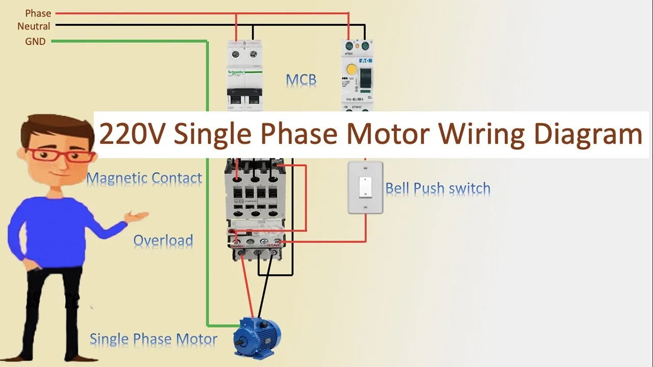
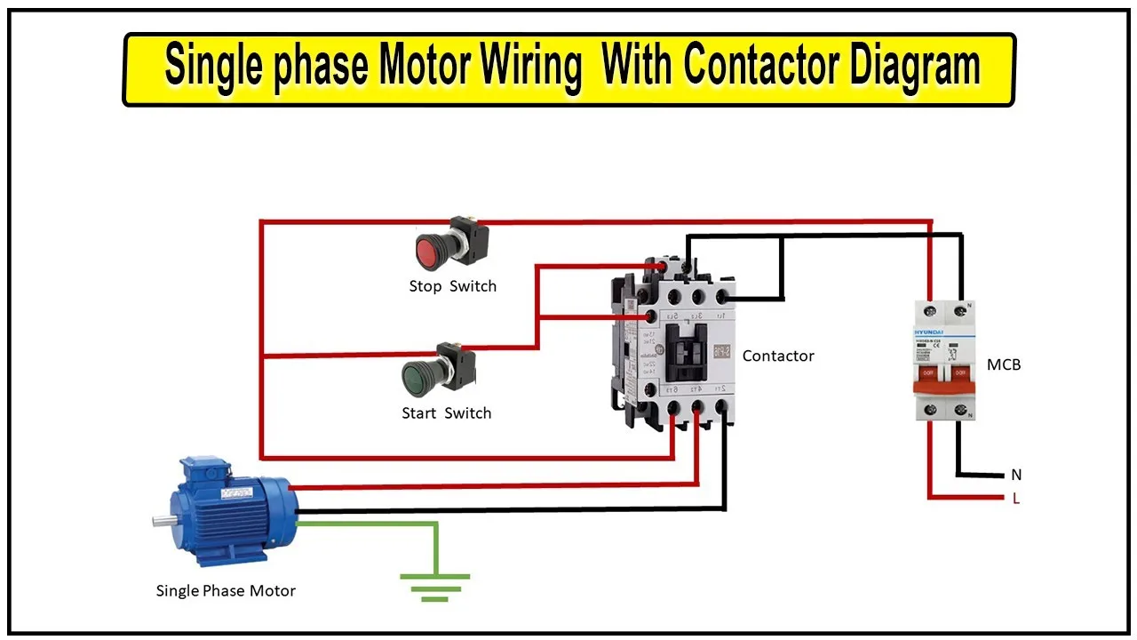
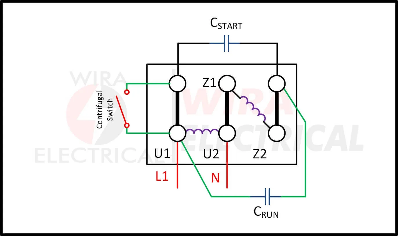
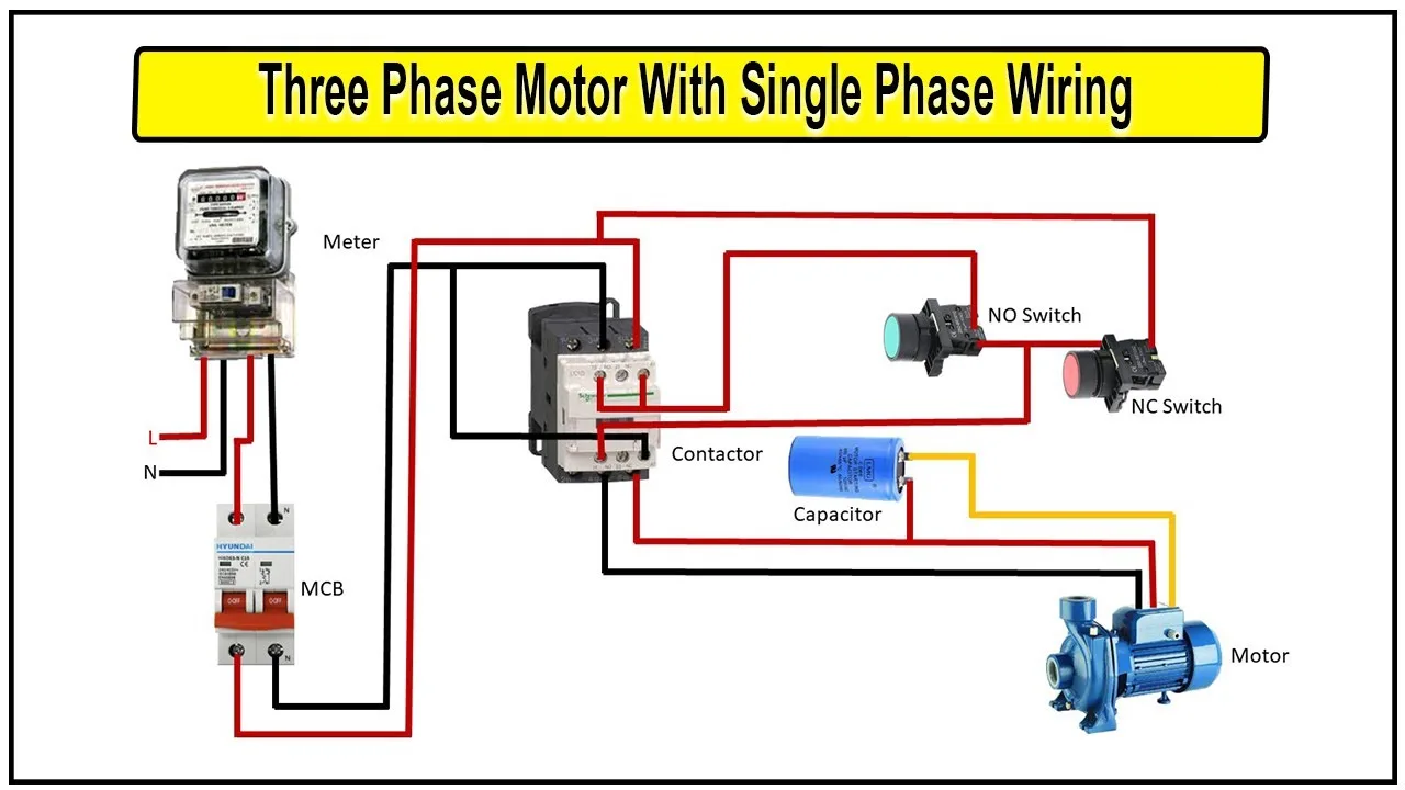
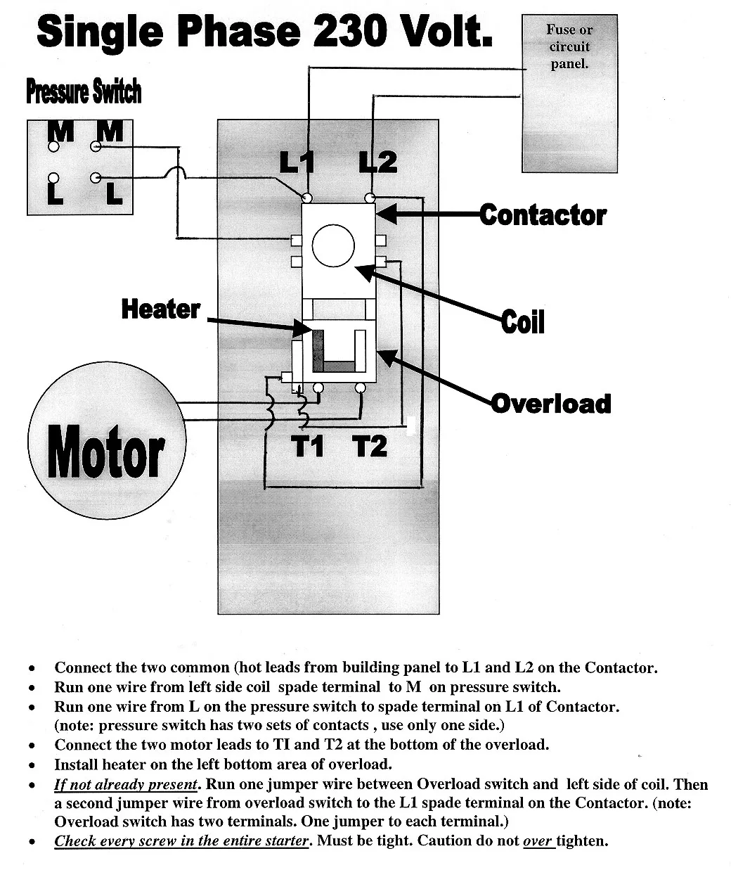
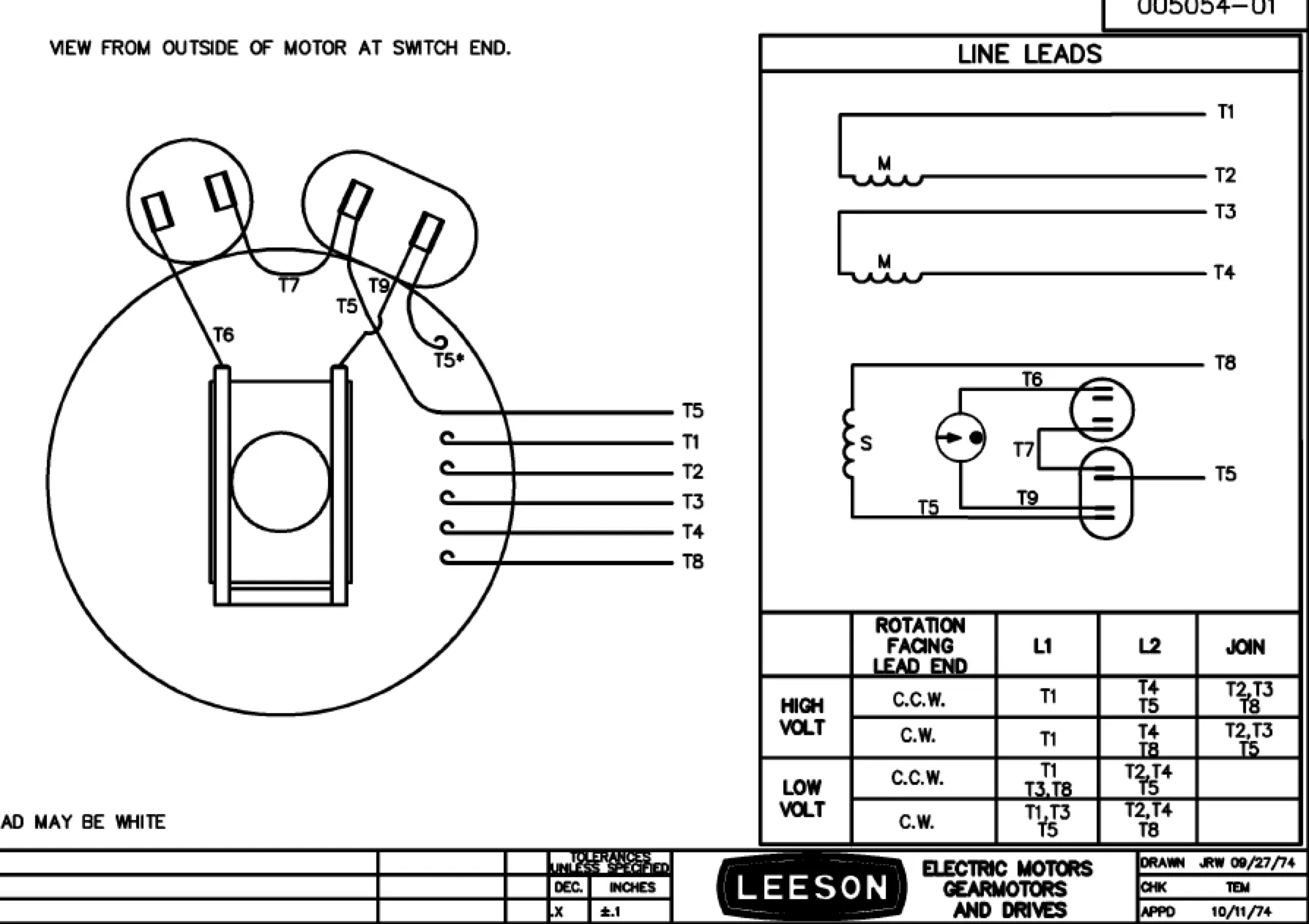
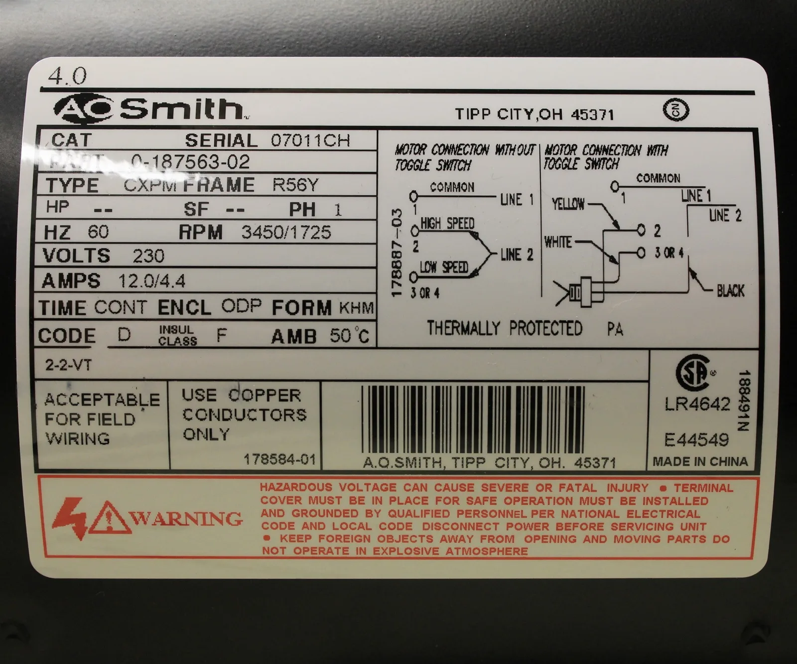
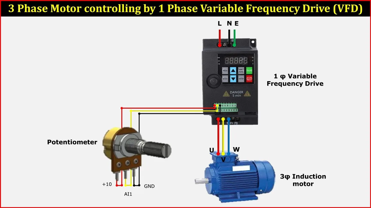
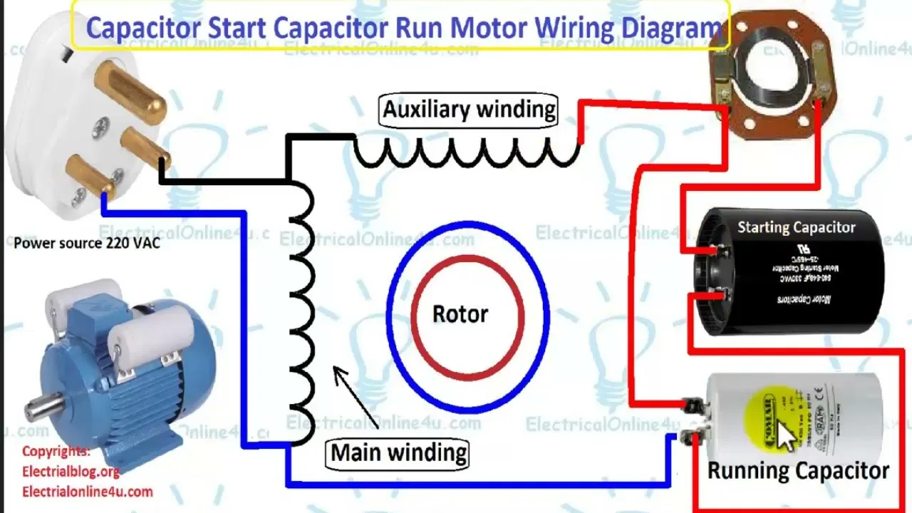
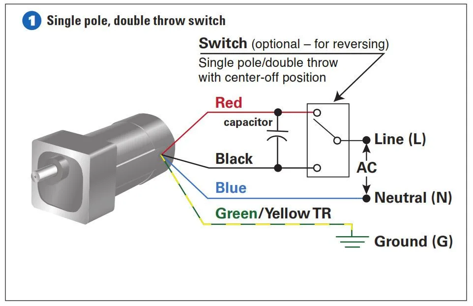
115 Volt Single Phase Motor Wiring Diagram Wallpapers
Related Images
More Images
Explore Topics 1
- Trailer Wiring Diagram Chevy Truck
- Rotork Wiring Diagram
- 1994 Suzuki Swift Transmission Diagram
- 2003 Chrysler Sebring Wiring Diagram
- Concrete Rebar Diagram
- 71 Kawasaki 125 Wiring Diagram
- 95 Ford Ranger 2 3L Engine Diagram
- Hdtv Cable Hookup Diagram
- 79 Ford F 1510Wire Diagram
- 91 Ski Doo Wiring Diagram
Explore Topics 2
- Chevy S110Pick Up Wiring Diagram
- Blinker Wiring Diagram For 1995 Buick Lesabre
- 4 Wire Trailer Plug Wiring Diagram
- 2016 Honda Hr V Wiring Diagram
- 2002 Chevy Impala 3 4 Engine Diagram
- 2006 Fusion Fuse Diagram
- Electric Fan Wiring Diagram With Relay
- 1999 Silverado Ac Wiring Diagram
- Maxima Engine Diagram
- Way Trailer Plug Wiring Diagram
Explore Topics 3
- 2001 Toyota Corolla Wiring Diagram
- 91 Ford Bronco Fuel Line Diagram
- 2003 Silverado Undercarriage Diagram
- Garage Door Opener Remote Control Circuit Diagram
- Solar Power Wiring Diagram On A Car
- Wiring Diagram Kenwood Kdc 2019
- 36 Volt Club Car Wiring Diagram 1984
- 1999 Ford F2510Fuse Box Diagram
- 35 Hp Johnson Outboard Wiring Diagram Free Download
- Wiring Diagram For 1988 Jeep Cherokee
Explore Topics 4
- Radio Wiring Diagram 2001 Dodge Caravan
- 20010Honda Odyssey Cooling Fans Wiring Diagram
- 2004 Arctic Cat 5010Wiring Diagram
- 20010Chevy Tracker Fuse Box Diagram
- Wiring Diagram Honda Civic Hybrid
- 2002 Ford Mustang Fog Lights Wiring Diagram
- 1966 Ford F1010Electrical Diagram
- 97 Cadillac Catera Wiring Diagram
- Broan Exhaust Fan Wiring Diagram
- Kia Sorento Bcm Wiring Diagram
Explore Topics 5
- Airstream 7 Pin Wiring Diagram
- Diagram Samsung S6 Edge
- 1Egc5 Dayton Relay Wiring Diagram
- Tractor Alternator With Voltage Regulator Wiring Diagram Free
- Ford F 2510Front Axle Diagram
- 2 P910Wiring Diagram
- Marine Wiring Diagram Yamaha F90
- Circuit Diagram Of 8 Bit Alu
- Wiring Diagram Power Window Timor
- Diagram Of Wiring 2006 Gmc Sierra Truck

