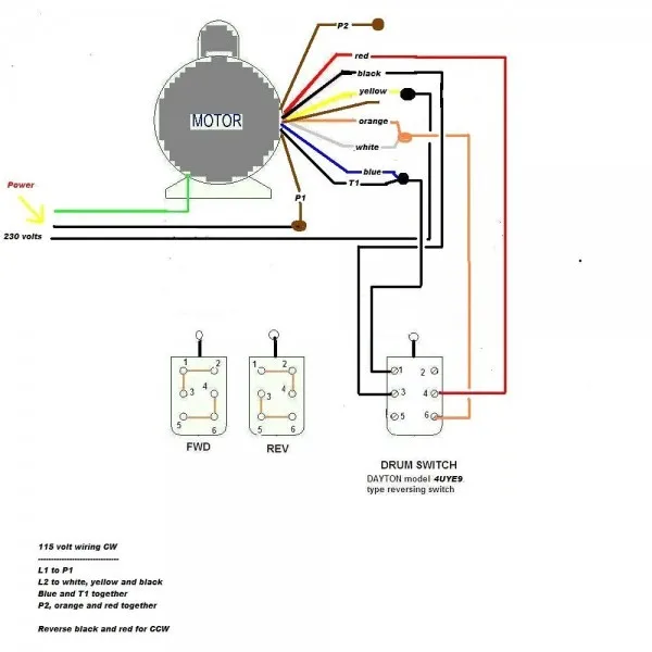
115 Volt Schematic Wiring Diagram Wallpapers

Related Images
More Images
Explore Topics 1
- 8 Wheel Horse Wiring Diagram
- Phoenix Wiring Diagram
- F2510Super Duty Wiring Diagram
- Suzuki Tu250X User Wiring Diagram
- 20010Mazda Millenia S Fuse Box Diagram
- 2006 Honda Accord Fuse Box Diagram
- Car Stereo Wiring Diagram Mazda
- Single Line Diagram Motor Starter
- Charger 48V Club Car Wiring Diagram
- Pontiac Grand Prix Fuse Diagram
Explore Topics 2
- Pearly Gates Humbucker Wiring Diagram
- 20010Ford Taurus Se Fuse Box Diagram
- Maintainer Wiring Diagram
- Ford E 3510Radio Wiring Diagram For 2008
- Wiring Diagram Gem 7 2V
- 97 Chevy Lumina Fuse Box Diagram
- Digital Gauge Wiring Diagram
- Ethernet Circuit Diagram
- 98 Ford Mustang Fuse Box Diagram
- 3 Phase Reversing Motor Wiring Diagram Single Pole Double Throw A Using
Explore Topics 3
- Monte Carlo Headlight Wiring Diagram
- 2006 Porsche Cayenne S Wiring Diagram
- Integra Automatic Transmission Wiring Diagram
- 1986 Ford Ranger Bronco Ii Truck Service Manual Set Oem Binder Style Service Manual And The Wiring Diagrams Manual
- 20110F2510Super Duty Wiring Diagram
- Seat Belt Diagrams
- Cherry Mx Red Diagram
- 1991 Geo Metro Transmission Diagram
- Contactor Wiring Diagrams
- 6610Grizzly 4Wd Wiring Diagram
Explore Topics 4
- Electrical Wiring Diagram Schematic
- 8N Spark Plug Wiring Diagram
- 1991 Oldsmobile Wiring Diagram
- 4 Wire 2210Volt Wiring Diagram For Uprightzer
- Volvo Truck Wiring Diagram Fm9 Fm12Fh12Fm
- 2015 2110Popular Electrical Systems Wiring Diagrams
- Clarion Cmd5 Wiring Diagram
- 8N Engine Diagram
- Fender Strat Hss Wiring Diagram
- 1997 Saturn Wiring Diagram
Explore Topics 5
- Electrical Wiring Residential Circuit Diagram
- Daylight Saving Light Sensor Wiring Diagram
- 2002 Lincoln Continental Power Seat Wiring Diagrams
- 4 20Ma Circuit Diagram
- Gm 3510Firing Order Diagram
- 2003 Ford E2510Fuse Box Diagram
- 20010Ford Expedition Parts Diagram
- 5 Wire Trailer Connector Diagram
- 2003 Tracker Fuse Diagram
- Cable Tv Splitter Wiring Diagram


