101 Wire Harness Diagram

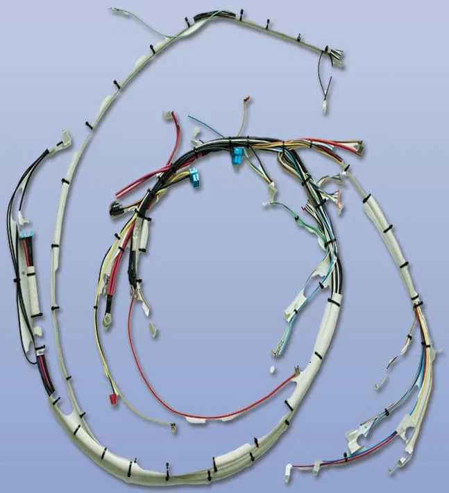
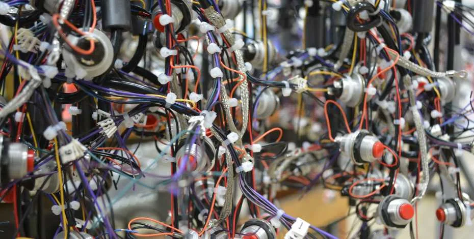
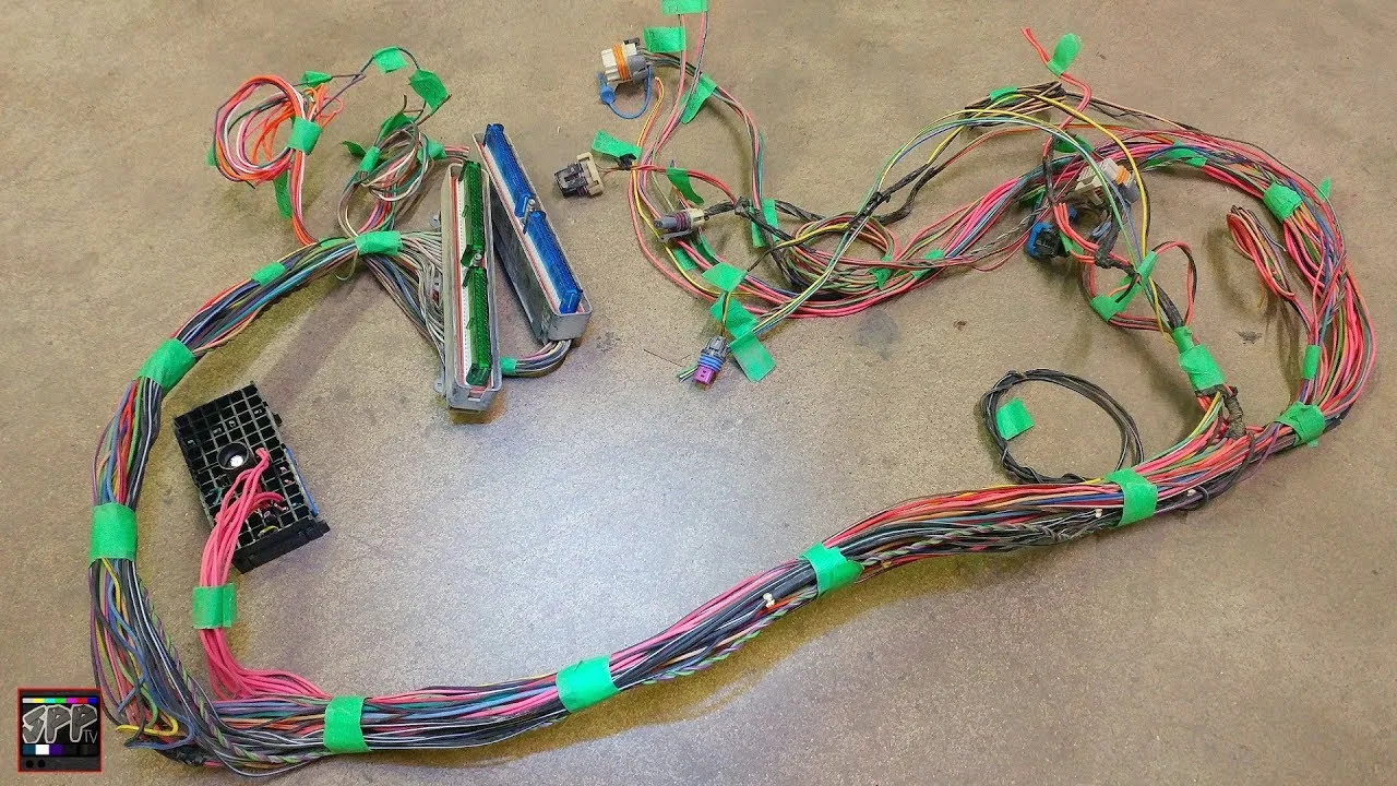
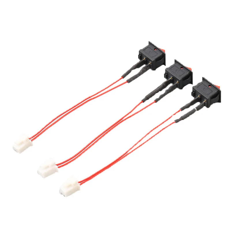
Wire harnesses are a vital component in any electrical system. They allow for the organization, protection, and transmission of electrical signals from one point to another. Wire harness diagrams are essential in understanding the inner workings of these complex systems.

What is a Wire Harness Diagram?

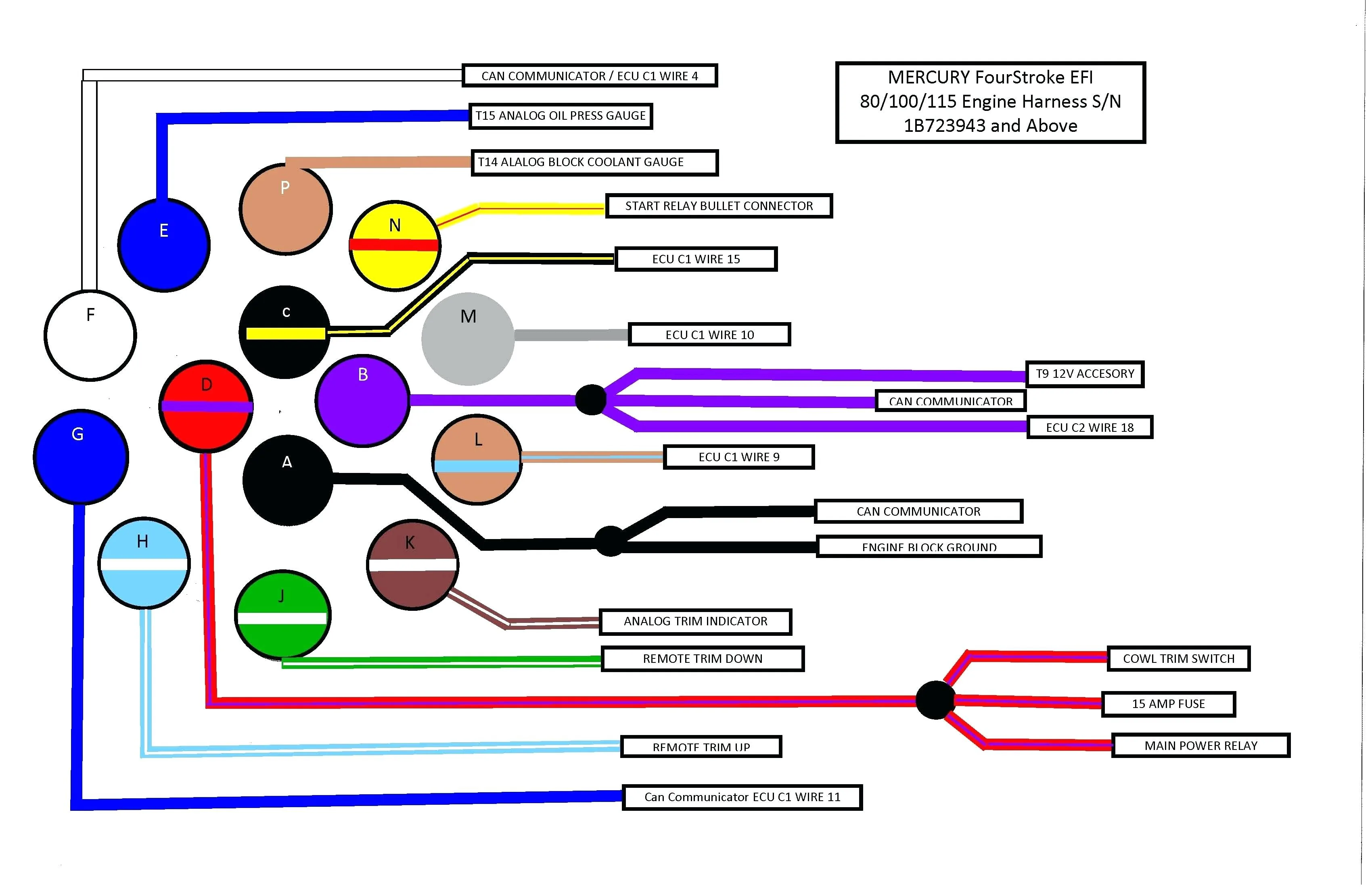
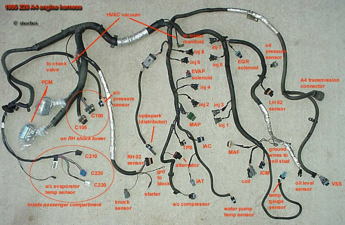
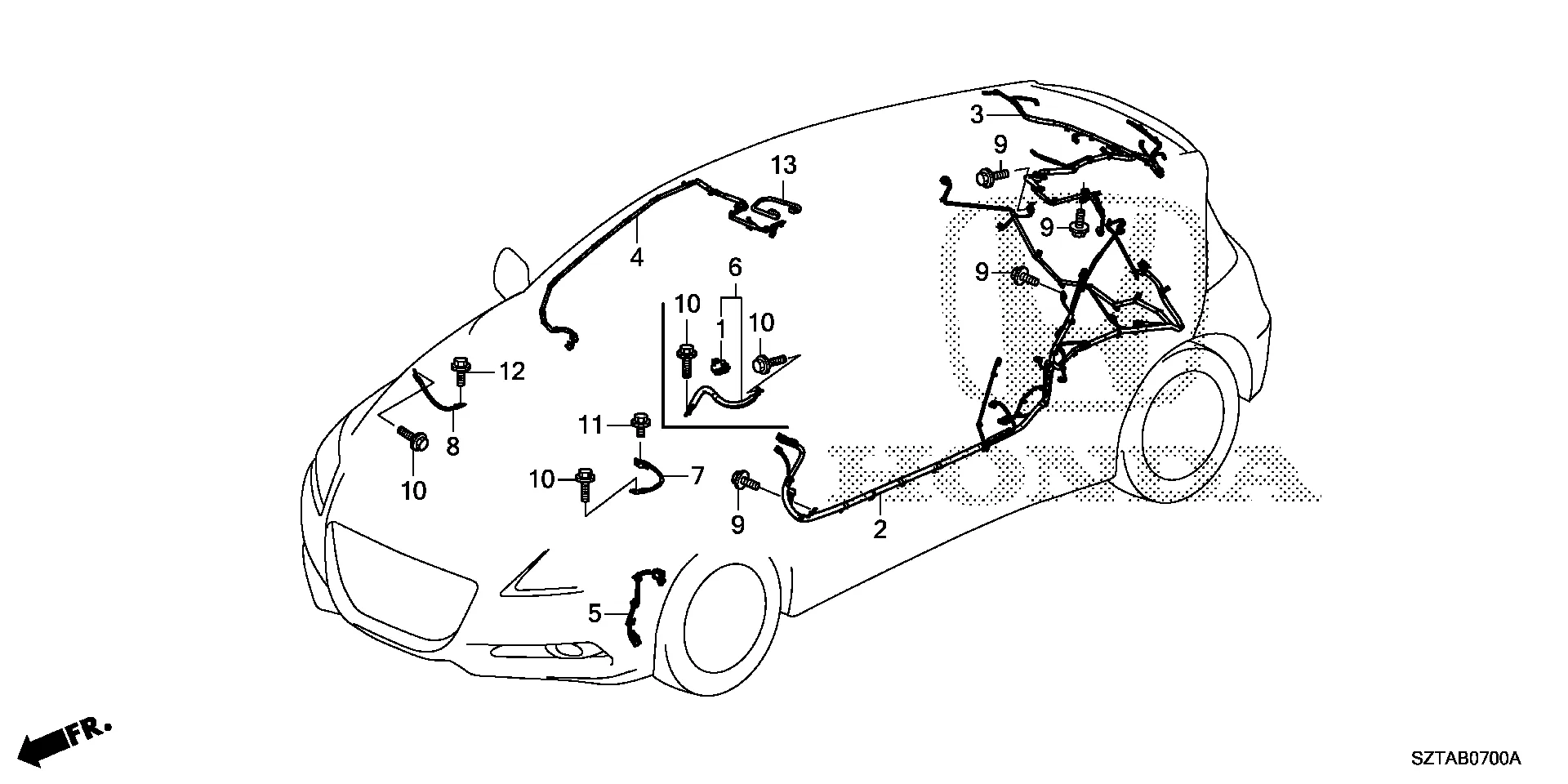
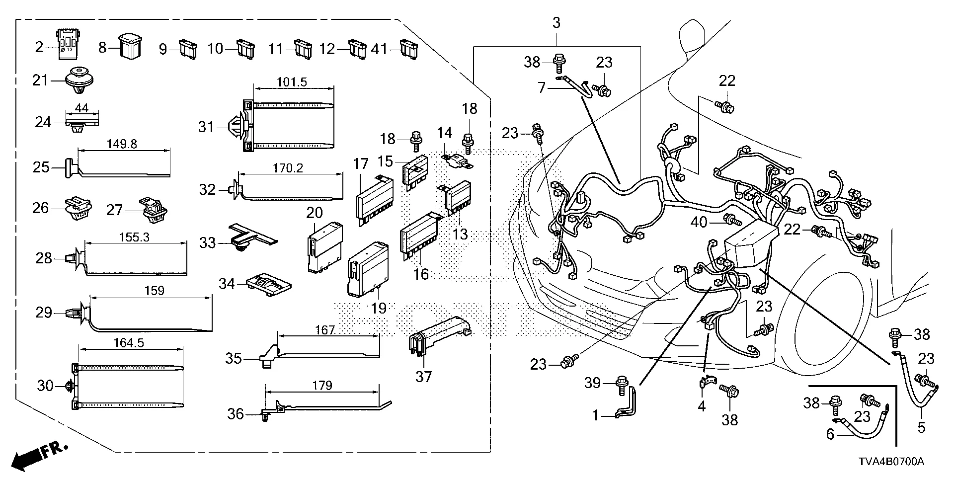
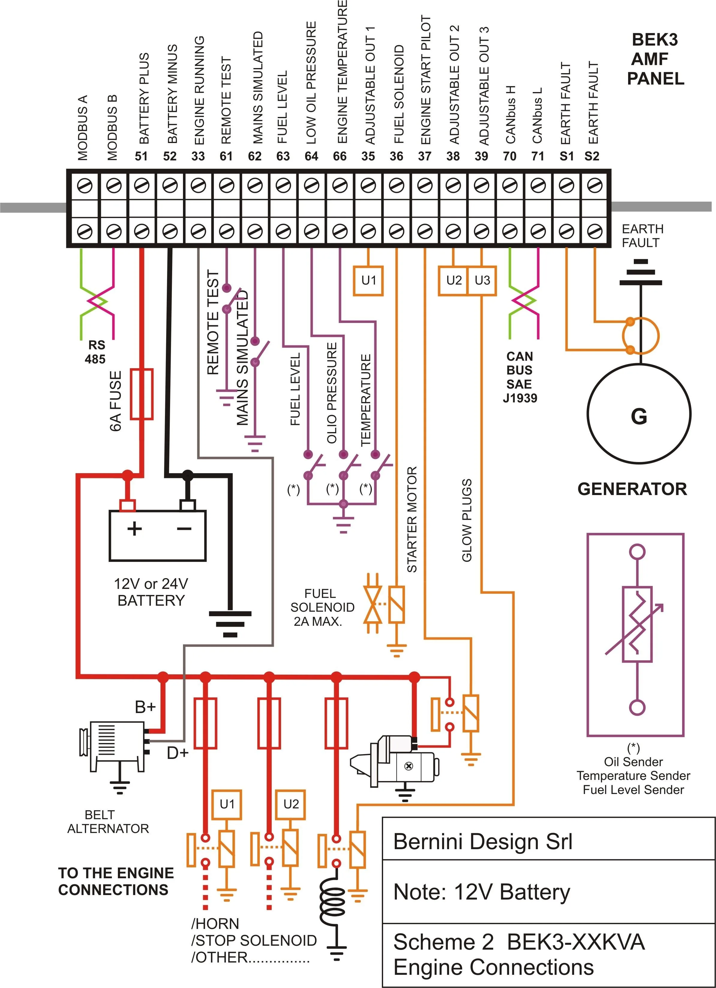
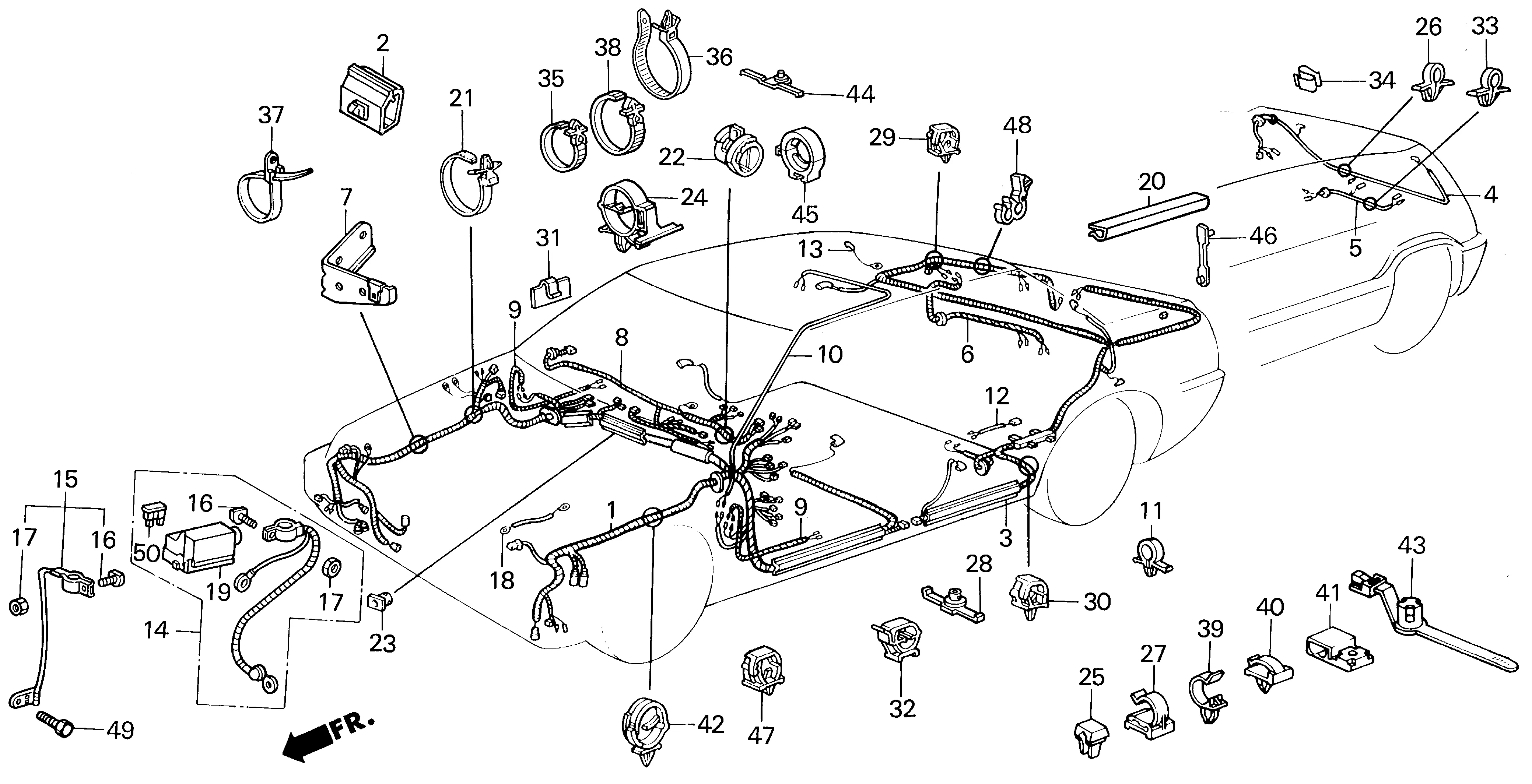
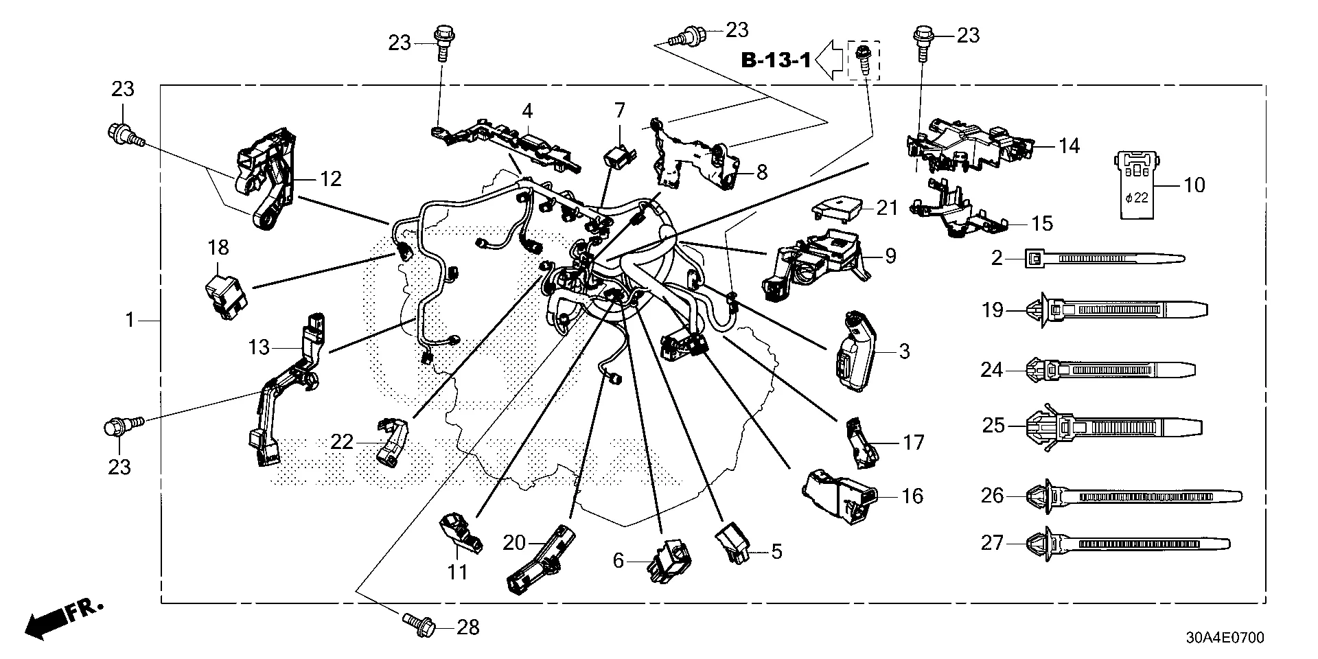
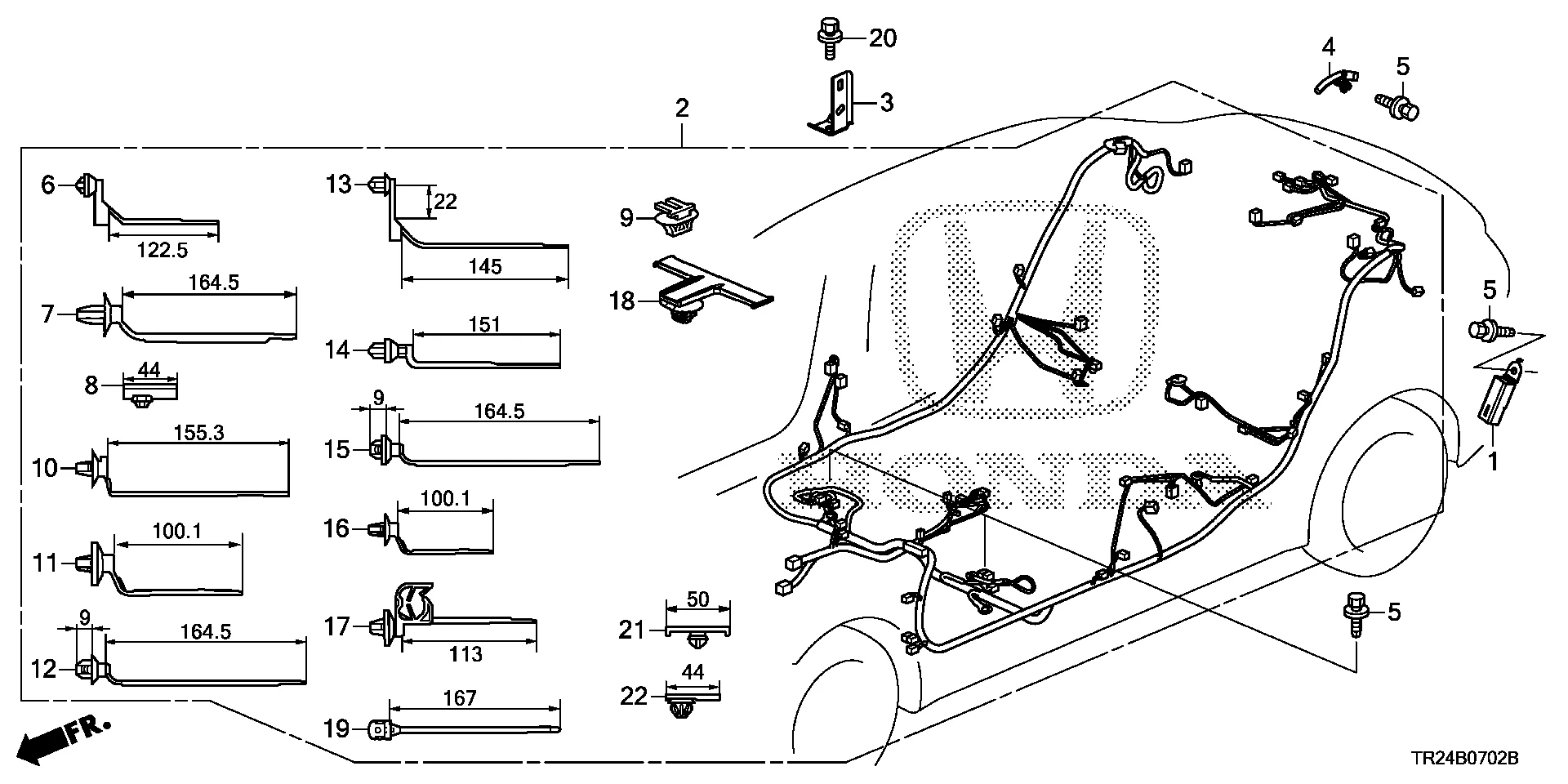
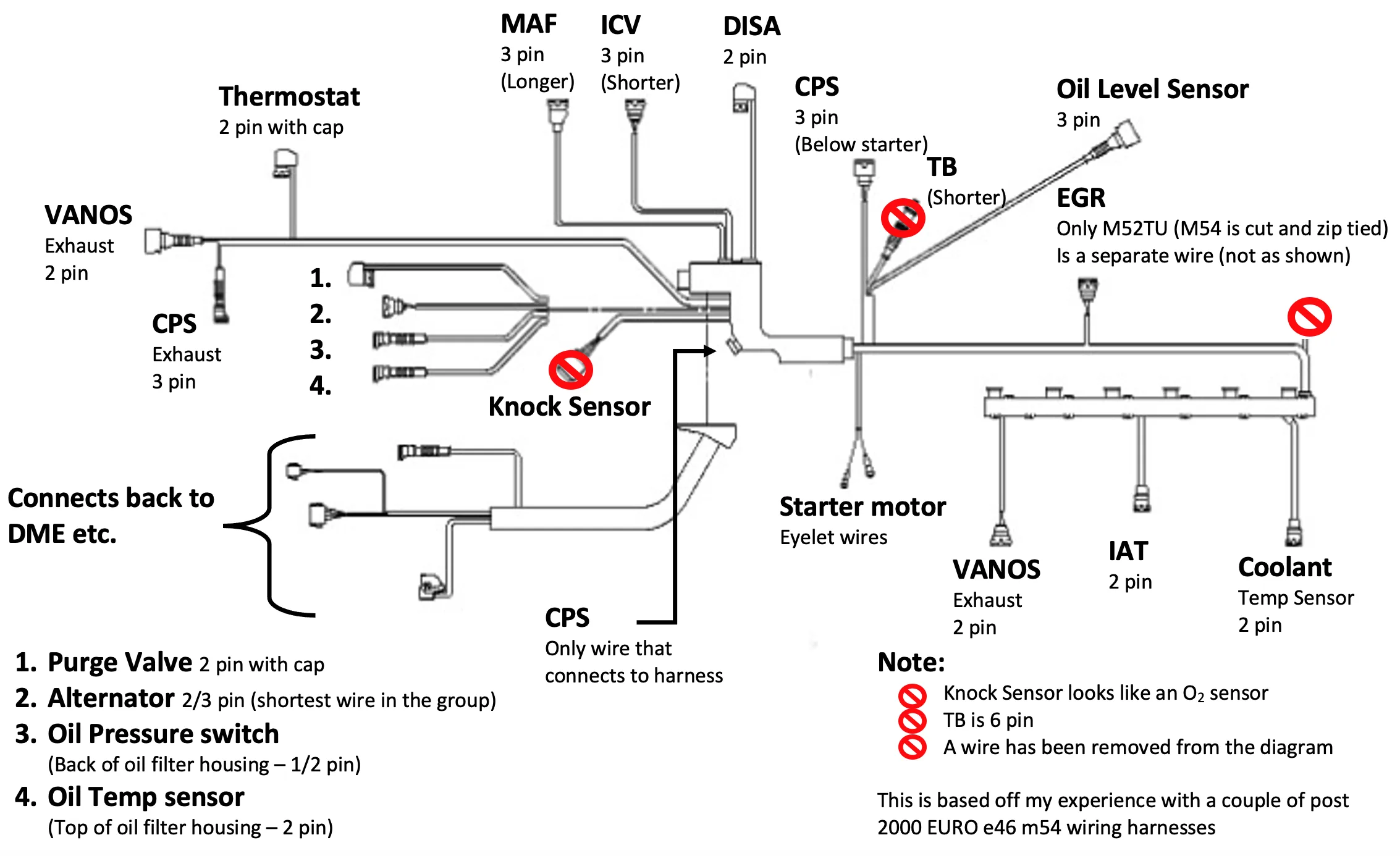
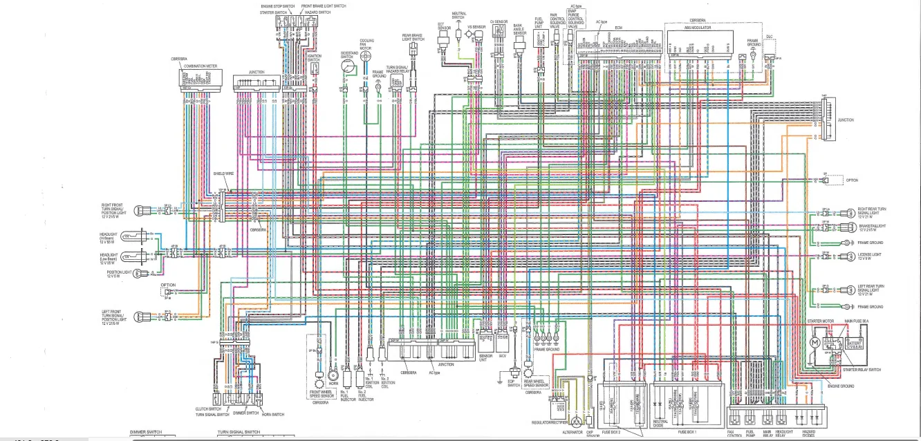
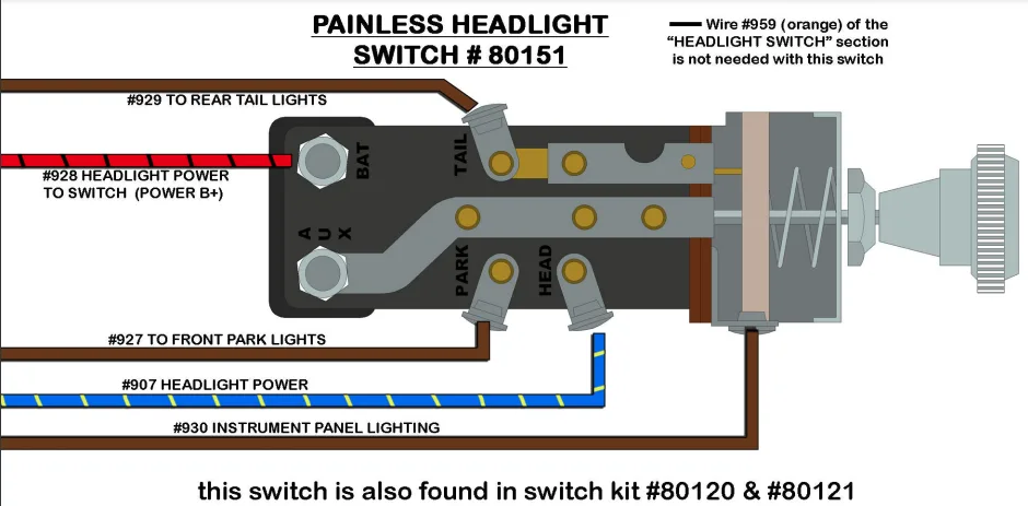
A wire harness diagram is a visual representation of the wiring configuration found in a wire harness. It outlines all the wires and connections within the harness and provides a roadmap for technicians and engineers to troubleshoot, repair, or replace the harness if necessary.

Wire harness diagrams vary in complexity depending on the system they are used in. For example, a wire harness diagram for a car may be much more intricate than one used in an electronic device.

Regardless of the complexity, wire harness diagrams provide an invaluable resource to any technician working with electrical systems.

Why Use a Wire Harness Diagram?

Using a wire harness diagram allows technicians to easily identify any issues within a system. They can quickly pinpoint the location of a faulty wire or connection and make the necessary repairs.

Additionally, wire harness diagrams ensure that all connections are properly made during assembly. If a wire is connected improperly, it can lead to system failure and even safety hazards.

Overall, using a wire harness diagram is a best practice in any electrical system.

The Basics of Wire Harness Diagrams

Wire harness diagrams consist of several key components.

Wire Color Code

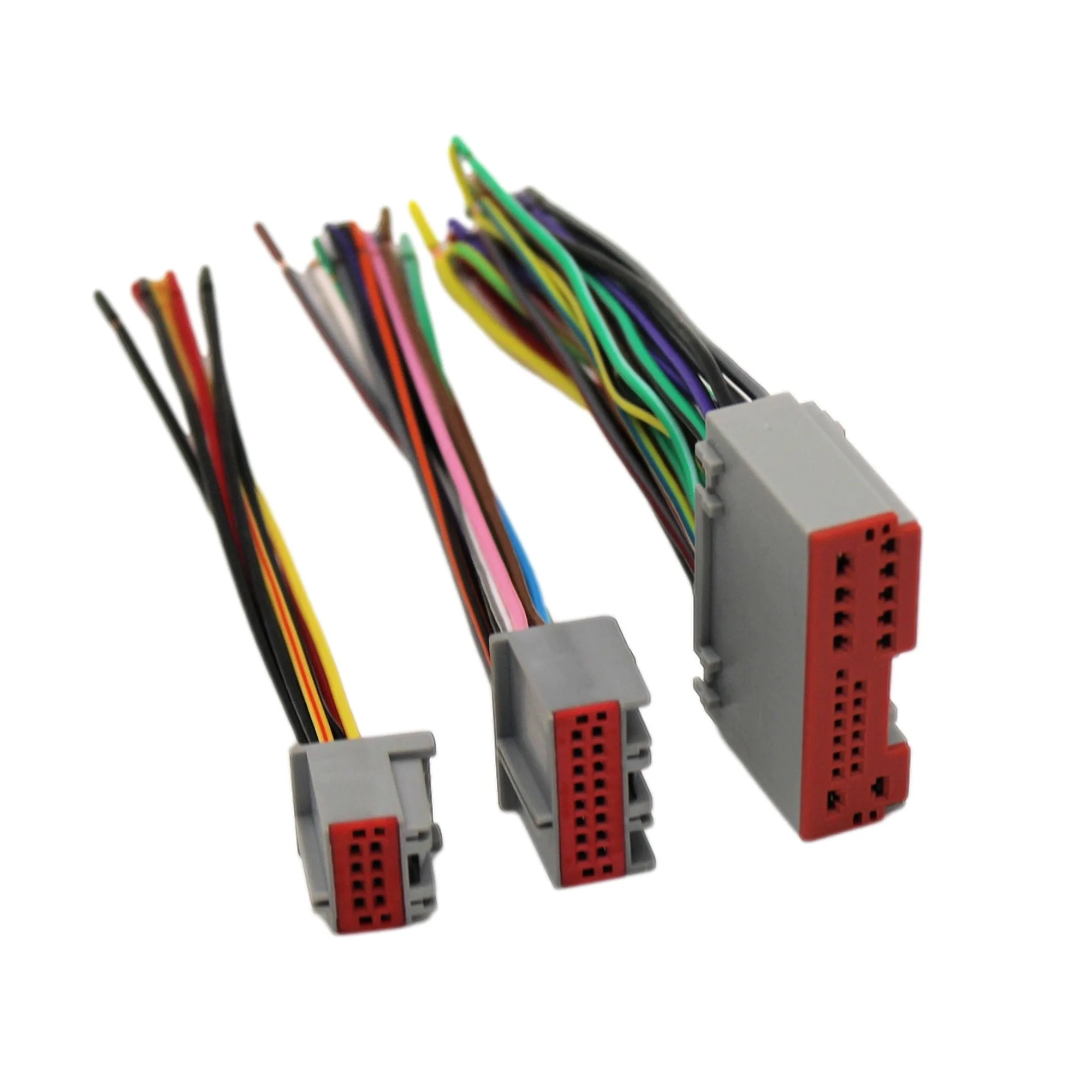
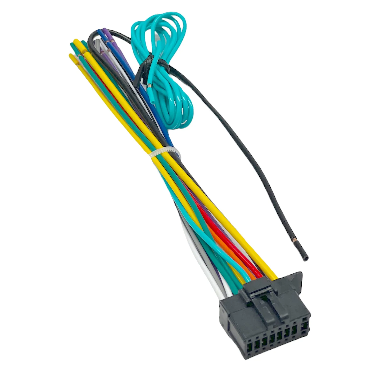
Wire color codes are used to identify specific wires within the harness. Each wire is assigned a specific color, allowing technicians to easily identify and differentiate each wire.

For example, in a car’s wire harness, the red wire may signify a power source, while the black wire may be used for grounding.

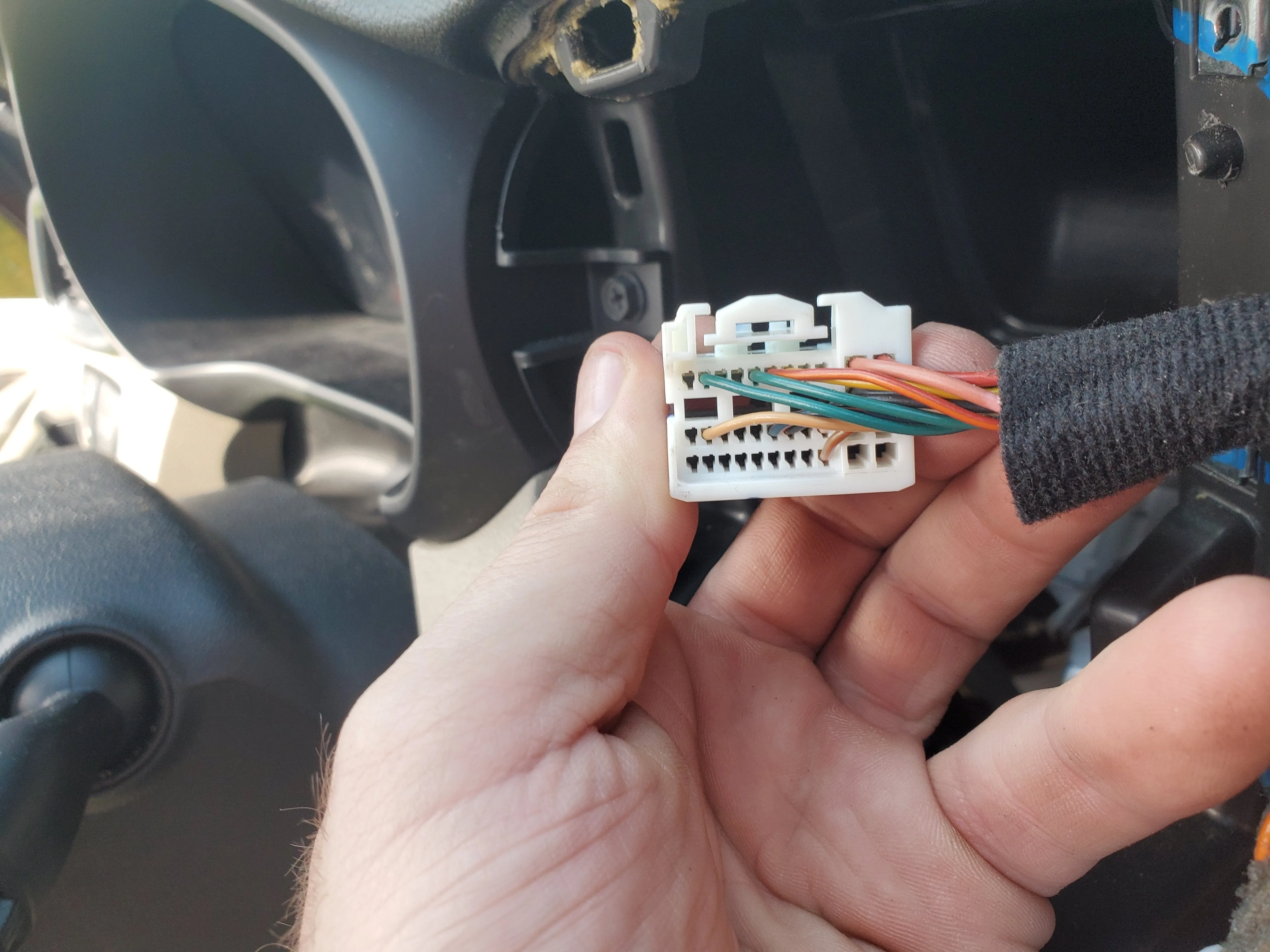
Connector Pinouts

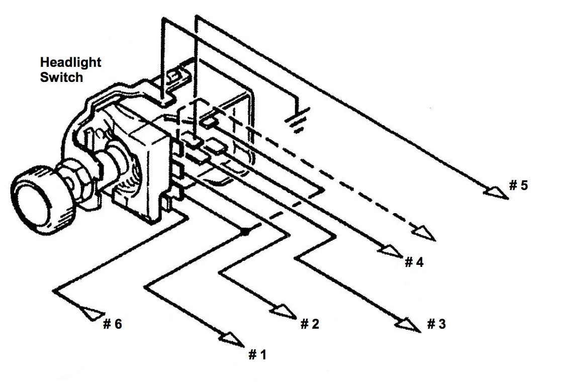
Connector pinouts indicate the location of each wire within the connector. They provide a reference for technicians to locate wires within the harness and ensure that they are connected correctly.

Schematic Diagram

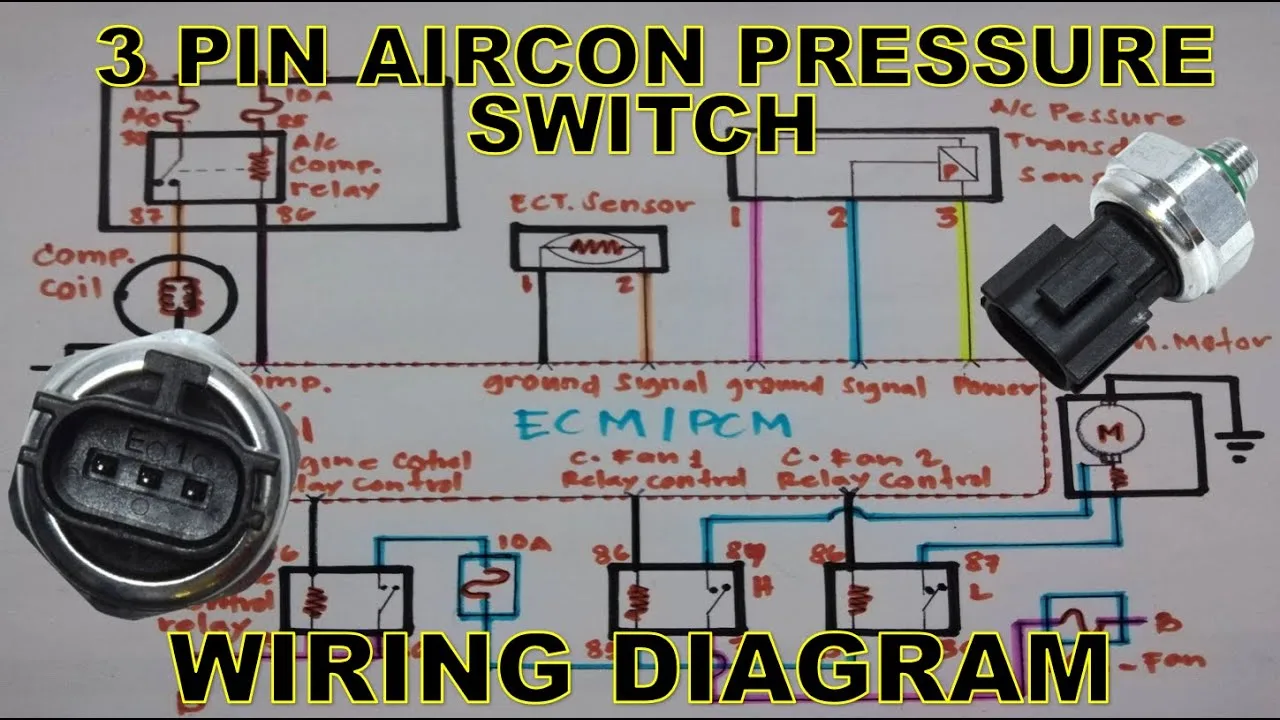
The schematic diagram provides a high-level overview of the wiring configuration for the system. It shows how each component is connected and how they work together to form the entire system.

FAQs

What Tools are Required to Read a Wire Harness Diagram?

Reading a wire harness diagram requires some basic tools such as a multi-meter, wire strippers, and a crimping tool. Additionally, it helps to have a basic understanding of electrical systems and wiring.

Can Wire Harness Diagrams be Used for Troubleshooting?

Yes, wire harness diagrams are an invaluable resource for troubleshooting electrical systems. They allow technicians to quickly identify faulty wires or connections and make the necessary repairs.

How Do I Create a Wire Harness Diagram?

Creating a wire harness diagram requires knowledge of the system and its components. It also requires a basic understanding of electrical wiring principles. If you are unsure of how to create a wire harness diagram, it is best to consult a trained technician or engineer.

Conclusion

Wire harness diagrams are essential in understanding and troubleshooting complex electrical systems. They provide a roadmap for technicians and engineers to easily identify and repair any issues within the system.

By using wire harness diagrams, you can ensure that your electrical systems are properly wired and functioning correctly.